


RC3000 Antenna Controller Chapter 2 Installation
60
2.4.4 Pulse Scale Factors
The pulse scale factors specify the number of pulses counted per degrees (in radians) of movement for
the azimuth and elevation axis. It is critical that these numbers are accurate since the tracking algorithms
use them to determine step sizes (in pulse counts). Note that the RC3000 counts both rising and falling
edges of the position pulses so that a single position pulse generates 2 position counts.
NOTE: In the majority of cases, the antenna scale factors will have already been characterized for
a mount and the appropriate values stored as defaults. The following procedures will only be
required if a condition exists (different gear ratios, different pulse sensors, etc.) exists.
The azimuth and elevation scale factors may be derived from the antenna mount manufacturer’s data or
from data measured by moving the mount.
SCALE FACTORS FROM MANUFACTURER’S SPECIFICATIONS
If the antenna manufacturer gives the position pulses per degree specification for the antenna’s azimuth
and elevation axis, simply multiply the value by 2 to obtain 'position counts per degree' (because the
RC3000 counts both the rising and falling edges of the position pulses). Multiply this 'position counts per
degree' value by 57.29 to obtain 'position counts per radian'. Round to the nearest whole number value
to obtain the Elev Constant CONFIG mode item.
Elev position pulses per degree _______ * 2 * 57.29 = _______ (position counts per radian)
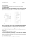
SCALE FACTORS FROM MOUNT MEASUREMENTS
The elevation scale factor is obtained by moving the antenna in elevation over a known angle (as
determined by an inclinometer) and obtaining the number of counts which corresponds to the angular
movement.
Here is the procedure:
Step 1. Identify a location on the antenna to place the inclinometer. The location on the mount should be
selected so that one degree of movement about the elevation axis registers as one degree on the
inclinometer. It is best to use an inclinometer which has a magnetic base. These are available in
hardware stores.
Step 2. Record the elevation position count and the reading of the inclinometer. These will be
designated CNT_1 and DEG_1, respectively.
Step 3. Jog the antenna in elevation. It is recommended that the antenna be moved 15 to 20 degrees in
elevation. Record the elevation position count and the inclinometer reading. These will be designated
CNT_2 and DEG_2.
The elevation region over which the measurements are made should correspond to the range of elevation
angles which will be encountered in operation (i.e. the elevation values over which the satellites will be
found).
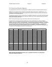
Step 4. Use the following formula to calculate the Elev Constant:
( (CNT_2 - CNT_1) / (DEG_2 - DEG_1) ) * 57.29
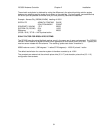
If the result is negative, change the sign to positive. Here is an example:
Inclinometer
Angle
Pulse
Count
Higher Position 50.2 32768
Lower Position 29.8 541
Difference 20.4 32227
(32227 / 20.4) * 57.29 = 9062 pulses/radian