


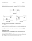
RC3000 Antenna Controller Chapter 2 Installation
46
NOTE: an alternate method for calculating the output signal from the inclinometer is to use the data
supplied by the inclinometer manufacturer for each individual inclinometer and multiply by the gain
(0.823) in the RC3000’s circuitry. (example: 59.27 mV/deg * 0.823 = 48.78 )
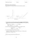
STEP 5. Up Limit Confirmation
Move the elevation axis to the UP physical limit and confirm that the “UP” limit is displayed in the
MANUAL mode.
Go to the Limits Maintenance screen (3.3.2.5) to confirm that the ELEV STOW and Down (DN) limits are
inactive.
If the state of the elevation STOW, DOWN and UP limits is not correct, check the limit switches and
wiring (2.2.4).
STEP 6. Software Elevation Limits
The DOWN and UP elevation limit values in the configuration screen should be set to reflect the physical
limits of elevation travel. Note that these limits don’t actually limit the elevation travel but are used by
software during the LOCATE function to determine if a calculated pointing solution is outside of the
mount’s range of movement. If a calculated pointing solution is beyond these limits, the message “ELEV
RANGE ERROR” will be displayed in the LOCATE screen.