


RC3000 Antenna Controller Chapter 2 Installation
48
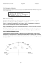
STEP 2. Initial Movement.
The next step is to move the azimuth axis to confirm drive and sensor polarity. Azimuth clockwise and
counterclockwise is defined as seen by an observer located above the antenna looking down on the
antenna.
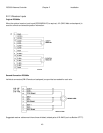
In MANUAL mode, when the AZ CW (6) key of the RC3000 is depressed the antenna motors must be
wired (see 2.2.2) so that the antenna moves clockwise.
The azimuth potentiometer or resolver should be wired so that clockwise movement results in a higher
azimuth position. When moving clockwise, the displayed azimuth position should increase.
STEP 3. Stow Limit Confirmation.
Move the azimuth axis clockwise and counterclockwise through the stow limit switch’s area of activation.
Confirm that the STOW indication appears and disappears in MANUAL mode.
Failure of the stow switch to deactivate would allow the reflector to potentially move below the elevation
DOWN limit in an unsafe manner. If the initial stow limit does not function correctly, check the limit switch
and wiring (2.2.4).
STEP 4. Clockwise and Counterclockwise Limits.
Discrete Limit Switches. Some mounts may mechanize azimuth clockwise and counterclockwise limits
via actual limit switches. If this is the case, move the azimuth axis through its range of motion and verify
that the CW and CCW limit indications appear in the MANUAL screen. After confirming these indications
move on to the next step.
Azimuth Electrical Limits. Other mounts may not have azimuth limit switches. In this case, the
RC3000 allows for the CW and CCW limits to be set based on the azimuth potentiometer voltage.
In this case, the antenna's azimuth electrical limits must be set. These limits are set using two
potentiometers on the controller's analog board and thus it will be necessary to remove the controller's
top cover. These two pots are labeled A-CW (azimuth clockwise) and A-CCW (azimuth counter-
clockwise). These 2 pots on the analog board are accessed via holes in the feature board. Note that the
Azimuth range limits specified below merely trigger the azimuth limit message and do not set the azimuth
motion limits for the antenna.
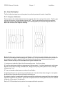
To set the azimuth clockwise limit, go to MANUAL mode and jog the antenna in azimuth to the desired
azimuth clockwise limit. If the controller indicates that the azimuth clockwise limit is reached before the
antenna reaches the desired position for that limit, the A-CW pot may have to be adjusted to allow the
antenna to move. Adjust the A-CW pot until the azimuth limit indication flickers between CW and blank.
To verify that the A-CW has been adjusted properly, verify that the antenna cannot move clockwise in
azimuth but can move counter-clockwise.
A similar procedure is used to set the azimuth counter-clockwise limit.
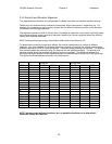
STEP 5. Azimuth Scale Factor.
NOTE: in most cases the default azimuth scale factor for a mount will be correct and should not
be changed. Perform this substep only if appendix B suggests that the azimuth scale factor for
your mount should be characterized.
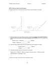
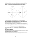
To calculate the azimuth scale factor, move the dish between two known physical azimuth positions and
note the difference in the sensed azimuth voltage between the two locations. If definite reference points
are available on the mount (+/-90 degree positions for example), these may be used. Otherwise use the
difference in azimuth pointing solutions to two satellites. Record the azimuth voltage at the peaked up
position of the two satellites.