


RC3000 Antenna Controller Chapter 2 Installation
58
2.4.3.3 Signal Strength Channel Calibration
This section describes the calibration procedure for a single channel. If two channels are to be used, the
procedure will need to be run for each. The procedure requires multiple steps and some steps are
iterative. The procedure also requires the use of a voltmeter (preferably with a resolution of millivolts).
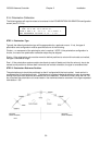
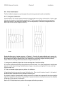
Step 1. Align the antenna with a strong satellite of the proper frequency band. Place a voltmeter on the
receiver’s signal strength output and record the voltage. The term “on satellite” will be used to refer to
the antenna aligned (peaked up) with a strong satellite.
ON SATELLITE VOLTAGE________________
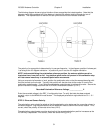
Step 2. Jog the antenna so the antenna is looking at nothing. Record the receiver’s signal strength
voltage. The term “off satellite” will be used to refer to the antenna positioned well off of any satellite
looking at nothing.
OFF SATELLITE VOLTAGE_______________
Step 3. Having recorded the On Satellite and Off Satellite voltages, go the SIG_ADJUST maintenance
screen (3.3.2.4). Enter the two voltages and record the polarity and voltage offsets calculated by the SIG
ADJUST screen.
POLARITY_____________ AGC1_OFFSET____________ AGC2_OFFSET_____________
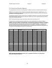
Note that the SIG ADJUST screen will calculate voltage offsets for both channels and suggest which
channel would be optimum for the entered On and Off Satellite voltages. Use the voltage offset for the
channel determined to be used for this receiver (see discussion above).
The calculated voltage offset will provide for the best transformation of signal strength input and will be
used in step 6 below.
Step 4. Go to the Signal Strength Factors configuration screen (3.3.1.2.5) and specify the polarity
required for the channel (1 or 2) that is currently being calibrated. This information will be used by the
RC3000’s software so that stronger signals will correspond to stronger indicated signal strength on the
RC3000’s displays.
Step 5. Go to MANUAL mode. Ensure that the channel that is currently being calibrated is displayed as
the signal source. If not, select the channel as the signal source by using the SCROLL DOWN / NO key.
Note that the displayed signal strength will currently be meaningless since the gain and offset calibration
steps have yet to be accomplished.
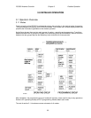
Step 6. Measure the offset voltage for the appropriate channel at the test point on connector J2 (refer to
2.2.5). Adjust the OFFSET pot for the appropriate channel until the value calculated in step 3 is obtained.
To increase the offset voltage turn the OFFSET pot clockwise (counterclockwise to decrease) when
looking at the backpanel.
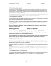
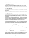
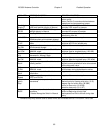
Step 7. Move back onto the satellite. Observe the displayed signal strength on the manual mode
screen. Adjust the GAIN pot for the appropriate channel until displayed signal strength of approximately
650 is obtained. The direction to turn the GAIN pot to increase displayed signal strength is dependent on
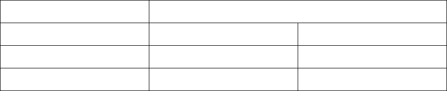
the characteristic of the signal strength input as indicated by the following table.
ON SATELLITE VOLTAGE
POLARITY Positive (>0) Negative (<0)
Positive CW CCW
Negative CCW CW