


RC3000 Antenna Controller Chapter 2 Installation
43
2.3.2 Elevation Calibration
Steps to perform elevation calibration will be described starting with the elevation axis in the stowed
position.
STEP 1.- STOW Limit Confirmation
With the elevation axis in the stowed position, go to the Limits Maintenance screen (3.3.2.5) to confirm
that the ELEV STOW and Down (DN) limits are active.
Also confirm that the elevation UP limit is inactive. If the UP limit is active, the RC3000 will be prevented
from moving the elevation axis up from the stowed position.
If the initial state of the elevation STOW, DOWN and UP limits is not correct, check the limit switches and
wiring (2.2.4).
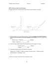
STEP 2. – Initial Movement
The next action is to raise the antenna in elevation. Push the UP key from MANUAL mode. The antenna
should rise. If not, check the polarity of the motor drive lines (section 2.2.2).
As the elevation axis comes out of the stow position, the STOW limit should inactivate but the DOWN limit
should remain active. This may be observed from the MANUAL screen by seeing the elevation “STOW”
indication change to a “DOWN” indication.
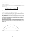
The elevation sensor should be mounted on the antenna so that the sense voltage produced at the
sensor increases as the antenna is jogged upward. In MANUAL mode, when the EL UP (2) key of the
RC3000 is depressed (and if the antenna moves up) the elevation position should increase (see section
2.2.3).
Note that the elevation position seen in the MANUAL screen might not initially change if the inclinometer
is still outside of its operational range or if the inclinometer is mounted on a feedboom that doesn’t rise
until the reflector has moved up a certain distance.
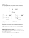
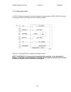
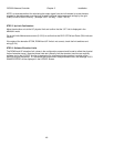
The following steps will require values to be entered in the ELEVATION CALIBRATION configuration
screen (see 3.3.1.2.2).
REF_V:1.69 OFF: 0.0 CONFIG-ELEV
DOWN: 0 UP: 90.0 SF:50.00
LOOK:1
SET REFERENCE VOLTAGE <0.50 – 3.50>
NOTE: the elevation offset item should be set to 0.0 before any further elevation calibration is
performed. Any required elevation offset will be determined during the azimuth and elevation alignment
step (2.4.2) as part of the final calibration steps. The LOOK configuration item is meaningful for only a
small number of mounts (see appendix B). In most cases the value of this item is irrelevant.