


RC3000 Antenna Controller Chapter 2 Installation
53
2.3.5 Fast/Slow Motor Speed
The fast and slow output voltages for your particular mount will be set at the factory and typically will not
need to be adjusted. On RC3000B models, there is only one fast/slow adjustment potentiometer on the
analog board. On RC3000A models, there are fast/slow adjustment potentiometers for each axis on the
auxiliary relay board next to the digital board.
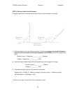
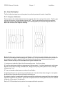
The slow speed for an axis should be set low enough that automatic movements perform smoothly. Care
should be taken that slow speed is not set so low that the axis is prone to jamming.
2.3.6 Pulse Sensor Checkout
This step resets and tests the pulse sensor system. It is only applicable for controllers that have software
options (such as inclined orbit tracking) requiring pulse feedback.
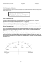
The first step is to position the mount to the appropriate place for resetting the pulse count (see appendix
B). After moving to this position initiate the pulse count reset from the DRIVE RESET maintenance
screen (see 3.3.2.2).
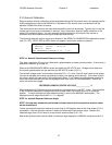
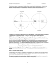
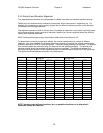
Next move the mount to the limits of azimuth and elevation travel and note the pulse count. The pulse
count can be viewed from the MANUAL screen by pressing the Scroll Up/Yes key. Record the pulse
count values at the four limits.
Azimuth CW Pulse Count______________ Azimuth CCW Pulse Count______________
Elevation UP Pulse Count______________ Elevation Down Pulse Count_____________
At the Azimuth Pulse Drive (3.3.1.7) and the Elevation Pulse Drive (3.3.1.10) configuration screens, enter
a value for the appropriate limit that is slightly within the recorded value. The value entered is within the
recorded value to account for any slop limit switches may exhibit.
NOTE that these pulse count limits are used by automatic movement routines such as tracking and spiral
search to limit the area of an automatic pulsed-based movement. These limits are not the actual
mechanism that will stop the mount’s movement.
2.3.7 Drive System Checkout
This step confirms the configuration of the drive system for all three axis. Manually move the mount to
each axis limit and confirm drive current to the motor is shut off when the limit is reached. Also check the
displayed position value and confirm that it is reasonable.
Perform the STOW (3.2.2.2) and DEPLOY (3.2.2.3) functions and confirm the mount correctly stows and
deploys.
STORE (3.2.2.4) several dummy satellites and RECALL 3.2.2.5 them to checkout the automatic drive
system. If the mount does not smoothly move to the target position, the drive parameters may have to be
adjusted.
2.3.8 Navigation Sensor Communication
If the optional GPS receiver and/or fluxgate compass are present, confirm that valid serial data is coming
from the unit(s). See the GPS COMM (3.3.2.6) or FLUX COMM (3.3.2.7) maintenance screen
descriptions.