


RC3000 Antenna Controller Chapter 2 Installation
29
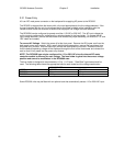
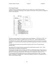
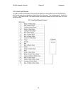
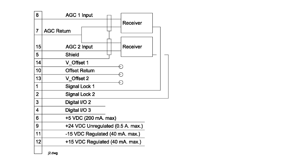
2.2.5 Signal Strength
J2 (DB-15 Female on backpanel) connects to receivers, modems, etc., to provide signal strength
indication for autopeaking and tracking. J2 also supports 4 bits of digital I/O and various bus voltages that
allow for future expansion.
The received signal strength from the system receiver must be between –15 VDC and +15 VDC. The
signal may be of either positive or negative polarity (see section 2.4.3 - signal strength adjustment).
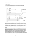
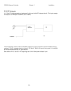
A shielded pair, such as Alpha 1292C, should be used to minimize external noise pickup on the signal
strength line. The shield should be connected at the RC3000 system ground and open circuited at the
receiver.
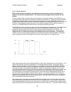
The offset test points need to be made available (flying leads, etc) for use in the signal strength
calibration step.
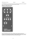
Associated with J2 are offset and gain potentiometers for signal strength channels 1 and 2. These
potentiometers are accessible via the back panel.
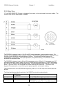
The two signal lock inputs require TTL level (<0.8 VDC-low, >3.5VDC-high) signals. Signal_Lock 1 is
associated with the AGC1 input (SS1) and Signal_Lock 2 with the AGC2 input (SS2). Either of the two
signal lock inputs may be associated with a RF autopeak scan as described in section 3.3.1.2.5.
The unregulated 24 VDC available at pin 9 may be used to provide DC bias to a LNB. This voltage
supply is protected by a resettable fuse. Please consult Research Concepts Inc. for assistance if you
wish to use this supplied voltage.