


k
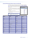
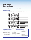
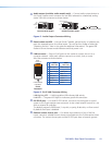
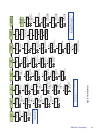
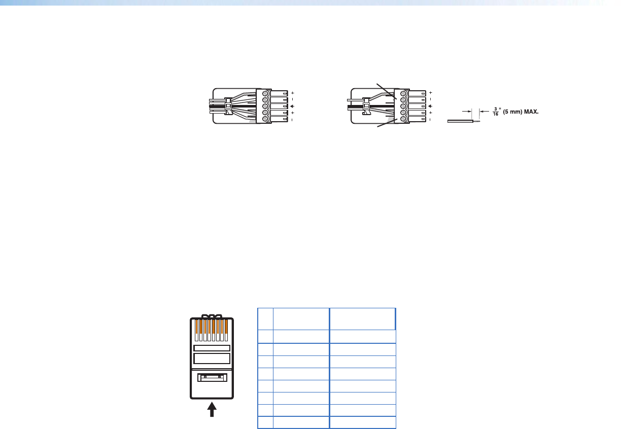
Audio output (variable, audio models only) — Connect audio output devices to
this 5-pole, captive screw connector for line level, balanced or unbalanced, analog
stereo. Wire the connectors as shown below.
Balanced Audio Output
Tip
Ring
Tip
Ring
Sleeves
Unbalanced Audio Output
Tip
No Ground Here
No Ground Here
Tip
Sleeves
LR
LR
Do not tin the wires!
Figure 5. Audio Output Connector Wiring
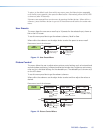
l
Reset button and LED — Using an Extron Tweeker, pointed stylus, or ballpoint pen,
press this recessed button for manual resets. The unit has four modes of reset (see
“Resetting the Unit” later in this guide for additional information). The green LED
ashes to show the reset mode indicators and that power is on.
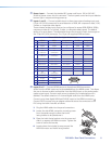
m
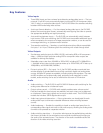
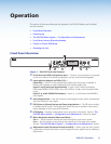
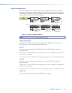
LAN connector — Plug an RJ-45 jack into this socket to connect the unit to a
computer network. Use a patch cable to connect to a switch, hub, or router.
Wire the connector as shown below.
12345678
RJ-45
Connector
Insert Twisted
Pair Wires
Pins:
Pin
1
2
3
4
5
6
7
8
Wire color
White-green
Green
White-orange
Blue
White-blue
Orange
White-brown
Brown
Wire color
T568A T568B
White-orange
Orange
White-green
Blue
White-blue
Green
White-brown
Brown
Figure 6. RJ-45 LAN Connector Wiring
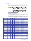
LAN Activity LED — A blinking yellow LED indicates LAN activity.
Link LED — The green LED lights to indicate a good LAN connection.
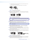
n
RS-232/IR port — For serial RS-232 control, connect a host computer or control
system to the 5-pole captive screw connector. Is also a hard wired IR control for use
with an external IR controller.
The default protocol is 9600 baud, 1 stop bit, no parity, 8 data bits, no ow control.
By default the IR port is disabled.
o
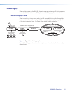
Remote contact closure port — For remote input selection of any of the ve
inputs, connect a suitable contact closure control device to this 5-pole captive screw
connector. The contact closure port and the RS-232 port share a common ground.
DVS 605 • Rear Panel Connections 10