


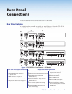
a
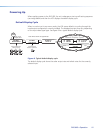
Power input — Connect the standard IEC power cord from a 100 to 240 VAC,
50-60 Hz power source into this connector. The front panel control and input selection
buttons light in sequence during power-up.
b
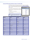
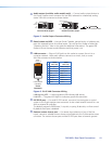
Inputs 1 and 2 — Connect suitable inputs to these two universal analog input ports
(15-pin HD [VGA] connectors) for auto-detection of RGB, HD component video, YUVi,
S-video, or composite video signals.
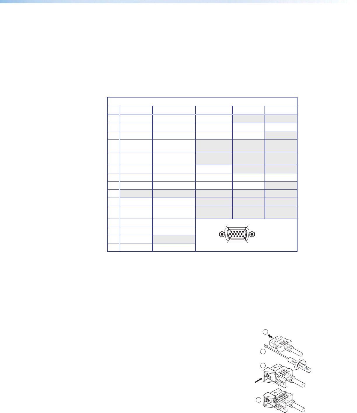
These universal analog input ports can be congured to accept RGB (RGBHV, RGBs),
component video (bi- or tri-level), S-video, or composite video signals. The default
setting is for auto detect. The table below shows the pinouts for each format type on
the 15-pin HD (VGA) connector. The 15-pin HD supports EDID emulation.
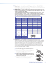
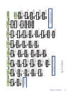
Pinout Table for 15-pin HD Connector
Pin RGBHV RGBs Component S-video Composite
1 Red Red R-Y
2 Green Green Y Luma Video
3 Blue Blue B-Y Chroma
4 No
Connection
No
Connection
5 No
Connection
No
Connection
6 Red Return Red Return R-Y Return
7 Green Return Green Return Y Return L Return Video Return
8 Blue Return Blue Return B-Y Return C Return
9
10 Ground Ground
11 No
Connection
No
Connection
12 EDID/DDC EDID/DDC
13 H Sync C Sync
14 V Sync
15 EDID/DDC EDID/DDC
c
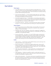
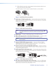
Inputs 3 to 5 — Connect HDMI sources to these three HDMI connectors.
Audio from the HDMI inputs can be de-embeded from the HDMI source. This allows
the user to choose to select audio either from the HDMI inputs or the analog audio
captive screw inputs. Once an audio source is selected, the unselected source is
disabled. The default selection is 2-channel digital audio from the HDMI inputs.
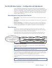
Connect up to three digital HDMI and DVD-D inputs to the HDMI connectors
c
.
Connect DVI-D sources using an adapter cable and secure the connectors to the
DVS using the LockIt
™
bracket as follows:
1. Plug the HDMI cables into the panel connections.
2. Loosen the side HDMI connection mounting screw
from the panel enough to allow the LockIt
lacing bracket to be placed over it.
3. Place the LockIt lacing bracket onto the screw and
slide it up against the HDMI connector. Tighten the
screw to secure the bracket.
4. Loosely place the included tie wrap around the
HDMI connector and LockIt lacing bracket.
15
11
15
3
4
2
1
DVS 605 • Rear Panel Connections 8