


Chapter 1 31
Getting Started
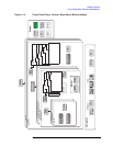
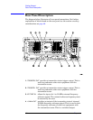
Rear Panel Description
5. TRIGGER IN The external trigger allows external triggering of
measurements. The external trigger accepts an
external trigger signal between
−5 and +5 V, and has a
nominal impedance of 10k
Ω. For more information on
triggering, see page 85.
6.
SCSI Currently the SCSI connection can only be used to
connect an external SCSI drive for firmware upgrades.
SCSI functionality will be fully implemented with a
future firmware update.
7.
Line Power Input AC power line connection. The line voltage operates
at nominally 115 V (47 to 440 Hz) or at nominally 230 V
(47 H to 66 Hz). The input power ranges for the power
supply are 90 to 132 V or 195 to 250 Vrms. The power
supply automatically senses the input power and
switches between these two ranges. There is no
customer replaceable power fuse. When on, the
instrument consumes less than 350 W; when in standby
less than 20 W.
8.
KYBD This feature is not implemented. This feature will be
implemented with a future firmware update. The
KYBD
enables connection of an external PS-2 keyboard using
a 6-pin mini-DIN connector. If no keyboard is available
you can use the numeric keyboard and the
Alpha Editor
menu key feature to make the entries. The keyboard
must be plugged into the instrument prior to powering
the instrument on or the keyboard will not work.
9.
GPIB The GPIB allows the connection of a General Purpose
Interface Bus (GPIB) cable, which enables remote
instrument operation.
10.
LAN-TP The LAN-TP connector can be used:
- as a SICL server emulating IEEE 488.2 protocol
over LAN.
- for a telnet programming port that can be sent
SCPI commands.
- for a TCP/IP socket programming port that can be
sent SCPI commands.
- for anonymous FTP operations to retrieve a screen
“gif” or screen “xwd” file from the ftp/pub.
NOTE For more information on remote programming with your transmitter
tester, refer to the programmer’s guide.