


158 Chapter 4
Making Measurements
Using Baseband I/Q Inputs (Option B7C)
The following table lists currently available Agilent probes which are
suitable for use under various measurement conditions:
Refer to the current Agilent data sheet for each probe for specific
information regarding frequency of operation and power supply
requirements.
The Transmitter Tester provides one “three-wire” probe power
connector on the front panel. Typically, it can energize one probe. If you
plan on operating more than one probe, make sure you provide
sufficient external power sources as required.
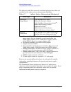
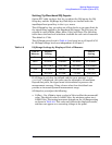
Table 4-7 Agilent Probes - Balanced and Unbalanced
Probe Type Description
Unbalanced
(Single Ended)
1144A 800 MHz Active Probe
abc
54701A 2.5 GHz Active Probe
cd
1145A 750 MHz 2-Channel Active Probe
abc
85024A High Frequency Probe
be
41800A Active Probe
bf
10020A Resistive Divider Probe
bc
54006A 6 GHz Passive Divider Probe
g
a. Not compatible with 3-wire power interface. Needs 1142A
power supply. For two channels, you will need either two
1142A power supplies or one 1142A power supply and one
01144-61604 1-input, two-output adapter cable.
b. Two probes needed to cover both I and Q inputs.
c. Output connector is BNC.
d. Not compatible with 3-wire power interface. Requires use of
1143A power supply. 1143A can power two 54701A probes.
e. 85024A bandwidth is 300 kHz to 3 GHz. Output connector is
type-N. Power is 3-wire connector (+15v/-12.6v/gnd)
f. 41800A bandwidth is 5 Hz to 500 MHz. Output connector is
type-N. Power is 3-wire connector (+15v/-12.6v/gnd)
g. 54006A output connector is 3.5 mm
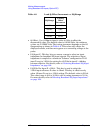
Balanced
(Differential)
1141A 200 MHz Active Differential Probe
abc
N1025A 1 GHz Active Differential Probe
bh
h. 3.5 mm output connector, requires +/- 15 volt supply