


146 Chapter 4
Making Measurements
Sensors
Sensors
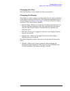
Purpose
The temperature of the RF board will vary over time and can adversely
affect the IF signal amplitude. Sensors on the RF board monitor
changes in temperature.
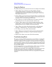
Measurement Method
The sensor measurements are generated internally and do not require
any user interaction.
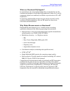
Test Setup
Press Mode, Service, Measure, Sensors.
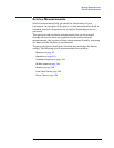
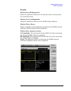
Results
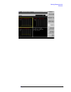
Window One (IF Signal Level)
Shows a stripchart of the IF signal amplitude in dBm.
Window Two (Cal Osc Level)
The Cal Oscillator window is not implemented.
Window Three (RF Temperature)
Shows a stripchart of the RF assembly temperature in Celsius.
Window Four (numeric results)
IF Signal Level: The ADC number for the detected 21.4 MHz IF
signal at the input to the AIF. Typical values with the input
attenuator set to 0 dB: 20 (no signal applied); 23(- 10 dBm); 27(- 5
dBm), and 38(0 dBm).
Cal Osc Level: Not implemented.
RF Temp: Shows current temperature in Celsius.