


Chapter 1 29
Getting Started
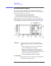
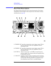
Front Panel Description
be implemented with a future firmware update.
18. On/Off switch turns on the transmitter tester. A green LED
will light below the
Power switch when the instrument
has been turned on. When in standby mode a yellow
LED is visible above the
On/Off switch.
19. Inputs enable you to input one or more of the two following
external signals.
•
I input and Q inputs. There are two I and two Q inputs
(I and I
−not; Q and Q−not). These connectors are
present if the BbIQ measurement personality
(Option B7C) is installed in your instrument.
•
External Trigger input. The external trigger allows
external triggering of measurements. The external
trigger accepts an external trigger signal between
−5 and +5 V, and has a nominal impedance of
> 10 k
Ω. For more information on triggering, see
page 85
.