


124 Chapter 4
Making Measurements
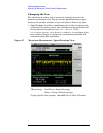
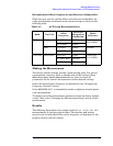
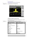
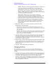
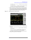
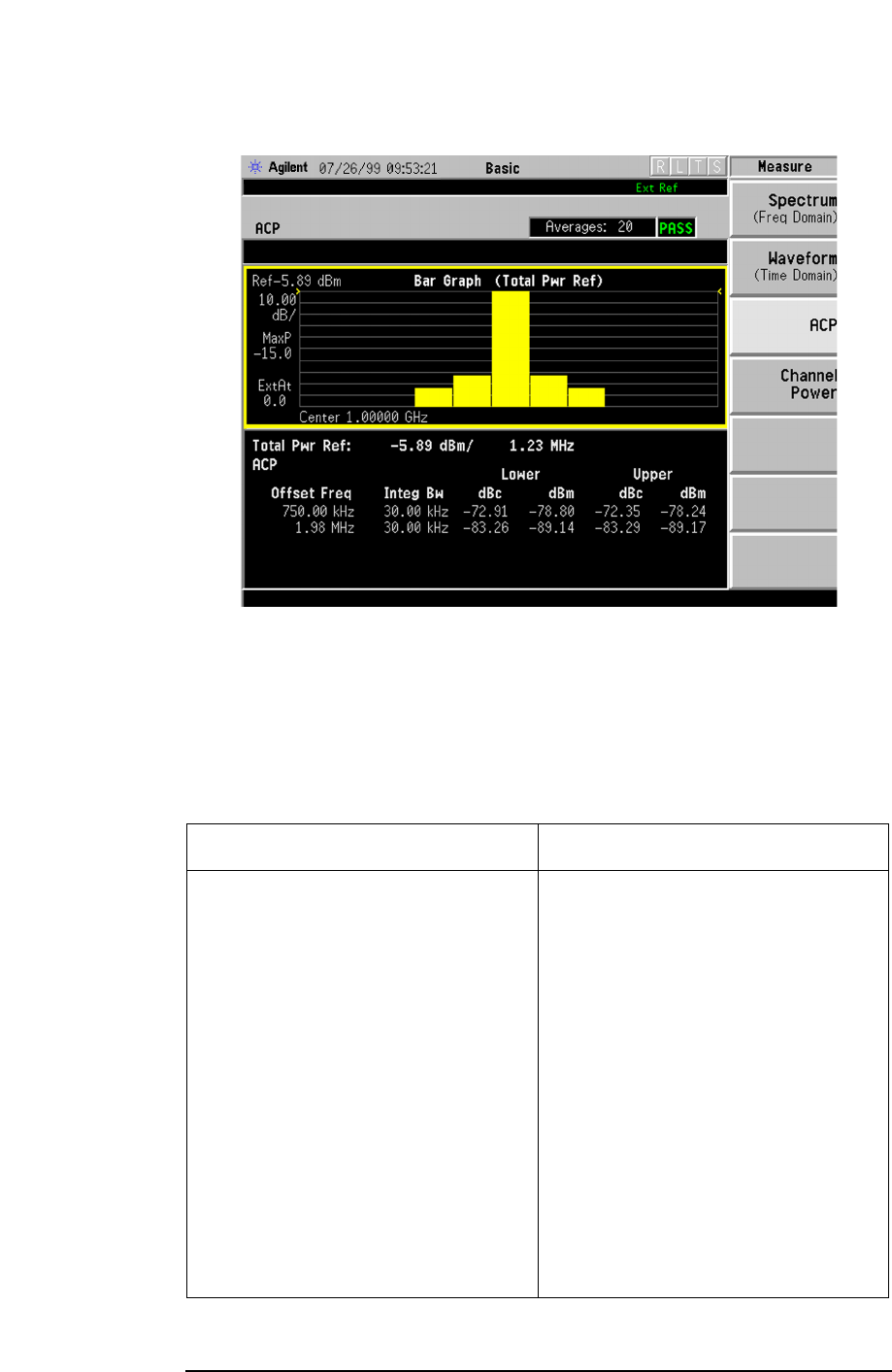
Making the Adjacent Channel Power (ACP) Measurement
Figure 4-10 ACP Measurement - Bar Graph View
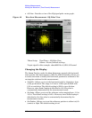
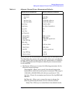
Changing the Measurement Setup
The next table shows the factory default settings for adjacent channel
power ratio measurements.
Table 4-4 Adjacent Channel Power Measurement Defaults
Measurement Parameter Factory Default Condition
View/Trace Bar Graph (Total Pwr Ref)
Spectrum Trace On
Averaging; Averaging Number On; 10
Avg Mode Repeat
Ref Channel:
Chan Integ BW
Avg Type
1.23000 MHz
Pwr Avg (RMS)
Offset/Limits:
Offset
Offset Freq
Offset Side
Ref BW
Avg Type
A
750.000 kHz; On (offset A)
Both
30.000 kHz
Pwr Avg (RMS)