


Chapter 4 Recording/Playback
46
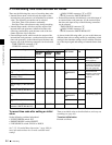
4-1 Recording
To record time code that follows
sequentially upon the last recorded time
code
You can record time code so that it is continuous from one
clip to the next on the disc.
Set the INT/EXT/RP188 switch to INT and the PRESET/
REGEN switch to REGEN beforehand. When this setting
is in force, the unit reads the time code of the last frame of
the last recorded clip on the disc before starting to record,
and internally generates time code that follows upon the
recorded time code.
In this case, the setting of extended menu item 628 “DF
MODE” is ignored. New time code is recorded in the drop-
frame mode of the last recorded time code on the disc.
To record with the internal time code
generator synchronized to external time
code
You can record with the internal time code generator
synchronized to time code input from an external device.
Use this method to synchronize the time code generators of
a number of recorders, or to carry out recording
maintaining the synchronization between the source video
and time code.
In this case, the settings of the F-RUN/R-RUN switch and
extended menu item 628 “DF MODE” are ignored.
You can synchronize the internal time code generator to
one of the following external time codes.
• TC input to this unit’s TC IN connector
• VITC in a video signal input to this unit
• SMPTE RP188 LTC in an SDI signal input to this unit
• i.LINK TC input to this unit’s S400 (i.LINK)
connector
• i.LINK VITC input to this unit’s S400 (i.LINK)
connector
Use the following procedure to synchronize the internal
time code generator according to the type of external time
code.
1
Make either of the following connections and settings.
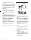
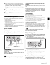
To synchronize to time code input to the TC IN
connector
Connect the time code output from the external device
to the TC IN connector. Press the VIDEO INPUT SEL
button and, while viewing the time data display or the
video panel, select one of SDI, COMPOSITE, or SG.
To synchronize to VITC in an input video signal
Connect a video signal containing VITC to the VIDEO
IN connector or the SDI IN connector. Press the
VIDEO INPUT SEL button and, while viewing the
time data display or the video panel, select
COMPOSITE or SDI.
To synchronize to SMPTE RP188 LTC in an SDI
signal
Connect an SDI signal containing SMPTE RP188
LTC to the SDI IN connector.
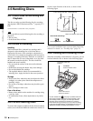
To synchronize to i.LINK TC
Connect an i.LINK signal to the S400 (i.LINK)
connector. Press the VIDEO INPUT SEL button and,
while viewing the time data display or the video panel,
select i.LINK.
To synchronize to i.LINK VITC
Connect an i.LINK signal to the S400 (i.LINK)
connector. Press the VIDEO INPUT SEL button and,
while viewing the time data display or the video panel,
select i.LINK.
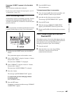
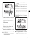
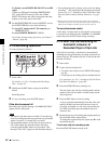
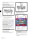
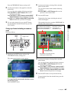
2
Make the following settings.
AUDIO
VIDEO
INPUT SEL
WARNING
KEY INHI REC INHI
INPUT CH INPUT SEL STATUS LIGHT MONITOR
HLOFFOFFON
OFFON
-30
dB
-12
-20
-40
-60
0
CH
- 15
DATA
OVER
-30
dB
-12
-20
-40
-60
0
CH-
26
DATA
OVER
-30
dB
-12
-20
-40
-60
0
CH-
37
DATA
OVER
-30
dB
-12
-20
-40
-60
0
CH-
48
BATT E F
DATA
OVER
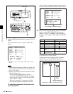
VITC
HOURS MINUTES SECONDS FRAMES
COUNTER HOLDVIUB
PB EXT-LKNDF
DISC E B
ACCESS
SHUTTLE JOG
THUMB
NAIL
ESSENCE
MARK
MENU
S.SEL
SET
RESET
SHIFT
TOP F REV
ALL/CH-1 CH-2 CH-3 CH-4
TC
F FWD
AUDI O
END
REC
PRESET
VARIABLE
PB
PREV NEXTPLAY STOP REC
CLIP
MENU
SYSTEM
MENU
MONITOR
SEL
METER
SEL
HOLD
COUNTER
SEL
SUB
CLIP
MARK1
MARK2
IN
OUT
KEY INHI
ON
OFF
NETWORK
LOCAL
REMOTE
F-RUN
R-RUN
PRESET
REGEN
INT
EXT
RP188
L/ST/R
CHARACTER
VITC
PROCESS
CONTROL
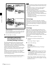
12
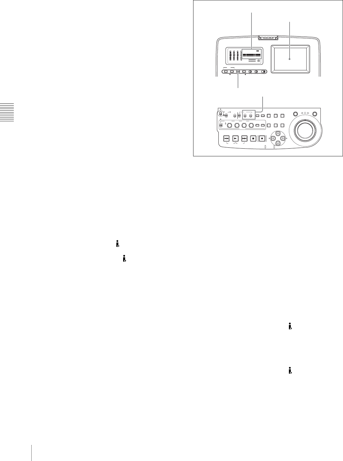
Time data display
Video panel