


Chapter 2 Names and Functions of Parts
22
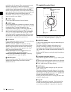
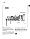
2-4 Connectors
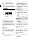
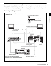
c REMOTE (remote control signal) connector (D-
sub 9-pin)
To control the PDW-R1 from a controller or VTR
supporting the RS-422A Sony 9-pin VTR protocol,
connect the device to this connector.
d REF VIDEO IN (reference video signal input)
connector (BNC type)
Input a reference video signal.
e (network) connector (RJ-45 type)
This is a 10Base-T/100Base-TX connector for network
connection.
To transfer files between an external device and the PDW-
R1, connect a network cable to this connector and the
external device.
Caution
For safety, do not connect the connector for peripheral
device wiring that might have excessive voltage to this
port. Follow the instructions in this manual when making
connections.
ATTENTION
Par mesure de sécurité, ne raccordez pas le connecteur
pour le câblage de périphériques pouvant avoir une tension
excessive à ce port. Suivez les instructions pour ce port.
ACHTUNG
Aus Sicherheitsgründen nicht mit einem Peripheriegerät-
Anschluss verbinden, der zu starke Spannung für diese
Buchse haben könnte. Folgen Sie den Anweisungen für
diese Buchse.
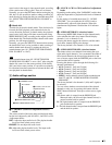
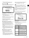
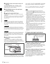
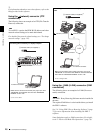
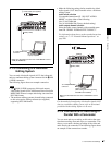
f S400 (i.LINK) connector (6-pin, IEEE1394
compliant)
Connect a DV device, computer, or similar, using an
i.LINK cable. To prevent the connector from coming
loose, we recommend that you secure the cable in the cable
clamp as shown in the following figure.
When the unit is shipped from the factory, the audio output
signal is set to 16 bit/48 kHz/2ch mode. You can change
the audio mode and output channel settings with extended
menu item 831 “DV OUT AUDIO MODE” and extended
menu item 828 “SDI/DV AUDIO OUTPUT SELECT.”
See 7-3-2 “Extended Menu Operations” (page 108) for
more information about how to make these settings.
Notes
• If video or audio signals from an external device
connected with the S400 (i.LINK) connector are not
output, disconnect the i.LINK cable and connect it again,
pushing it straight in.
• When the PDW-R1 is connected to a device with a 6-pin
i.LINK connector by an i.LINK cable, before
unplugging the i.LINK cable, first power off the device
and disconnect the power plug from the outlet. If the
i.LINK cable is unplugged with the device power plug
still connected, a current from an excessive voltage (8 to
40 V) output from the i.LINK connector of the device
flows into the PDW-R1. This may cause a failure of the
PDW-R1.
• When connecting the PDW-R1 to a device with a 6-pin
i.LINK connector, connect to the 6-pin i.LINK
connector of the other device first.
• Except in playback mode (jog and shuttle modes, etc.), if
you are monitoring the audio signal output from this
connector on another device, the audio signal may sound
differently from the audio signal played back on the
PDW-R1.
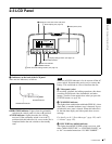
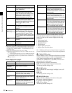
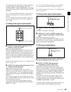
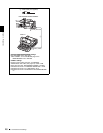
1 Digital audio signal inputs/outputs
a DIGITAL AUDIO (AES/EBU) IN (digital audio
input) 1/2, 3/4 connectors (BNC type)
These input AES/EBU format digital audio signals. The
left connector (1/2) corresponds to audio channels 1 and 2,
and the right connector (3/4) corresponds to audio
channels 3 and 4.
b DIGITAL AUDIO (AES/EBU) OUT (digital audio
output) 1/2, 3/4 connectors (BNC type)
These output AES/EBU format digital audio signals.
When the unit is shipped from the factory, the 1/2
connector is set to audio channel 1/2, and the 3/4 connector
is set to audio channel 3/4. You can change these settings
with extended menu item 827 “AES/EBU AUDIO
OUTPUT SELECT.”
REF VIDE
O
REMOTE
S400
DC OUT 12V
VIDEO
IN OUT1 OUT2(SUPER
To i.LINK (IEEE 1394)
connector of DV device or PC
Cable clamp
i.LINK cable
(not supplied)
DIGITAL AUDIO (AES/EBU)
IN 1/2 3/4 OUT 1/2 3/4
1 DIGITAL AUDIO (AES/EBU) IN 1/2, 3/4 connectors
2DIGITAL AUDIO (AES/EBU)
OUT 1/2, 3/4 connectors