


Chapter 2 Names and Functions of Parts
24
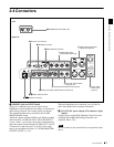
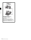
2-4 Connectors
“AUDIO CONFIG”-“NON-AUDIO INPUT” (recording)
and extended menu item 823 “NON-AUDIO FLAG PB”
(playback).
See 7-3-2 “Extended Menu Operations” (page 108) for
more information about how to make extended menu
settings.
See 7-4-2 “Maintenance Menu Operations” (page 114)
for more information about how to make maintenance
menu settings.
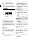
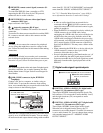
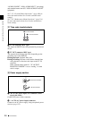
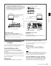
5 Time code inputs/outputs
a TC IN connector (BNC type)
This inputs an SMPTE time code generated by an external
device.
b TC OUT connector (BNC type)
This outputs the following time code, depending on the
operating state of the PDW-R1.
During playback: playback time code
During recording: the time code from the internal time
code generator or the time code input to the TC IN
connector.
When extended menu item 611 “TC OUTPUT
PHASE IN EE MODE” is set to “muting,” no time
code is output.
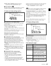
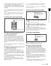
6 Power supply section
a DC IN (DC power input) 12V connector (XLR
type, 4-pin, male)
Connect DC power to this connector.
b - AC IN (AC power input) connector
Connect to an AC power supply, using an optional power
cord (see page 133).
TC
IN OUT
1 TC IN connector
2 TC OUT connector
AC IN
DC IN
12V
1 DC IN 12V connector
2 -AC IN connector