


Chapter 2 Names and Functions of Parts
20
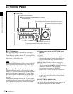
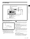
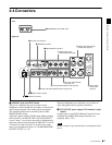
2-3 LCD Panel
a) This appears when a disc is loaded, and the format of a clip recorded on
the disc is different from the format specified by basic menu item 031 or
the setting of the “AUDIO CONFIG” - “DATA LENGTH” item in the
maintenance menu.
b) 9PIN: When extended menu item 214 is set to “9PIN”
i.LINK: When extended menu item 214 is set to “i.LINK” and menu item
215 is set to “AV/C”
— — —: When extended menu item 214 is set to “i.LINK” and menu item
215 is set to “FAM” (remote control from a device connected to the
S400 (i.LINK) connector is not possible when this combination of
settings is in force)
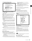
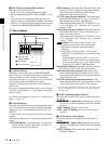
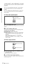
Items displayed on page 2
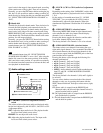
When you press this button with the SHIFT button held
down, the process control screen appears in the video
panel. You can use this screen to adjust the following
parameters.
• Video output level
• Chroma output level
• Setup/black level
• Chroma phase
• Output signal sync phase
• Output signal subcarrier phase
See “Adjusting video processing parameters” (page 49)
for more information about how to make the adjustments.
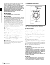
b CHARACTER switch
Selects whether or not to superimpose the time code, menu
settings, alarm messages, or other text information on the
video signals output from the side panel SDI OUT
(SUPER) and VIDEO OUT 2 (SUPER) connectors and
also on the unit’s video panel.
ON: Superimpose character information.
OFF: Do not superimpose character information.
The factory default setting is ON.
c LIGHT switch
Selects whether the status display backlight is on or off.
ON: On.
OFF: Off.
The factory default setting is ON.
d MONITOR switch
Selects whether to display video in the video panel.
H: Display with high brightness.
L: Display with low brightness.
OFF: Do not display.
The factory default setting is H.
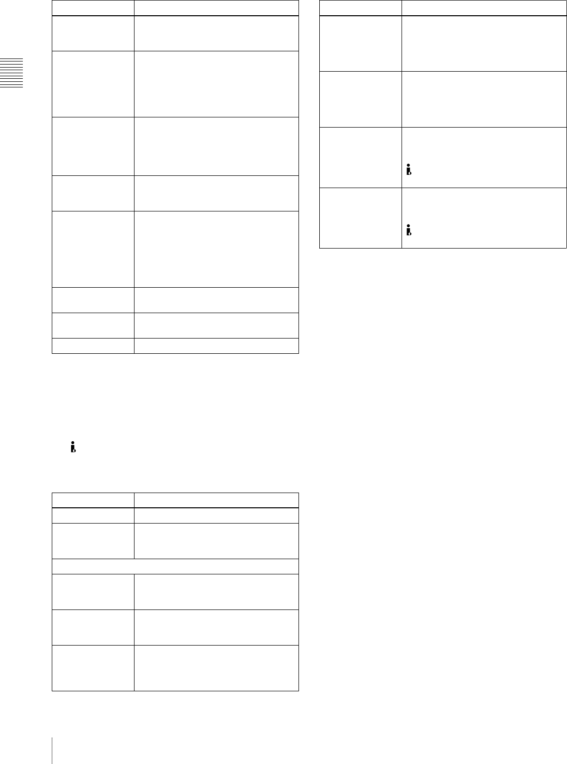
PROC This appears when at least 1 video
processing parameter has been set to
“VAR (VARIABLE).”
DISC
a)
The line mode of the current clip on the
disc (setting values: 525, 625), the
video recording format (setting values:
IMX50, IMX40, IMX30, DVCAM), and
the number of audio recording
channels (setting values: 8ch, 4ch)
RMT When the remote control switch is set
to REMOTE, the control interface
selected with extended menu item 214
(setting values: 9PIN, i.LINK,
— — —)
b)
PARA This appears when the parallel
recording with camcorder function is
enabled.
AC IN
DC IN ??.?V
BATT ??% (??.?V)
The type of power supplied to this unit
(AC IN: AC power, DC IN: DC power,
BATT: battery pack). The voltage (units:
V) appears when DC power is used,
and the remaining battery charge (unit:
% or V) appears when the battery pack
is used.
??MIN Free capacity remaining on disc (unit:
minutes)
??? Playback order number of clip being
played back
??h??m??s?? Duration of clip being played back
Item Description
VIDEO INPUT Same as VIN on page 1
AUDIO INPUT n
(n: channel
number 1 to 4)
Same as AINn on page 1
AUDIO OUTPUT
MONITOR L/R Audio channels selected with AUDIO
MONITOR SEL button (setting values:
tr1/2, tr3/4, tr5/6, tr7/8, MENU)
(MONITOR)
L/ST/R
Monitor channel selected with SHIFT +
AUDIO MONITOR SEL button (setting
values: STEREO, R, L)
ANALOG 1/2 Audio channels (setting values: tr1/2,
tr3/4, tr5/6, tr7/8) assigned to the
AUDIO OUT 1/3, 2/4 connectors with
extended menu item 824
Item Description
AES/EBU 1/2 Audio channels (setting values: tr1/2,
tr3/4, tr5/6, tr7/8) assigned to the
DIGITAL AUDIO (AES/EBU) OUT 1/2
connectors with sub item 1 of extended
menu item 827
(AES/EBU) 3/4 Audio channels (setting values: tr1/2,
tr3/4, tr5/6, tr7/8) assigned to the
DIGITAL AUDIO (AES/EBU) OUT 3/4
connectors with sub item 2 of extended
menu item 827
SDI/DV 1/2 Audio channels (setting values: tr1/2,
tr3/4, tr5/6, tr7/8) assigned to channels
1 and 2 of the SDI OUT (SUPER) and
S400 (i.LINK) connectors with sub
item 1 of extended menu item 828
(SDI/DV) 3/4 Audio channels (setting values: tr1/2,
tr3/4, tr5/6, tr7/8) assigned to channels
3 and 4 of the SDI OUT (SUPER) and
S400 (i.LINK) connectors with sub
item 2 of extended menu item 828
Item Description