


Chapter 2 Names and Functions of Parts
23
2-4 Connectors
To treat the input and output signals of these connectors as
non-audio signals, set the maintenance menu item
“AUDIO CONFIG”-“NON-AUDIO INPUT” (recording)
and extended menu item 823 “NON-AUDIO FLAG PB”
(playback).
See 7-3-2 “Extended Menu Operations” (page 108) for
more information about how to make extended menu
settings.
See 7-4-2 “Maintenance Menu Operations” (page 114)
for more information about how to make maintenance
menu settings.
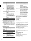
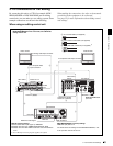
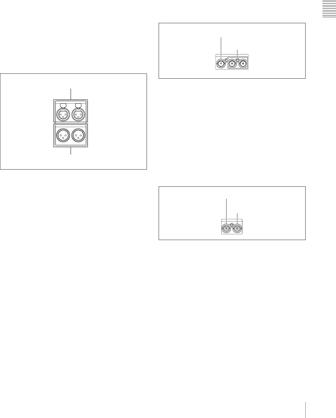
2 Analog audio signal inputs/outputs
a AUDIO IN (analog audio signal input) 1/3, 2/4
connectors (XLR 3-pin, female)
These input analog audio signals.
With the AUDIO INPUT SEL button (see page 19), you
can select whether the signal input to connector 1/3 is
assigned to audio channel 1or 3, and whether the signal
input to connector 2/4 is assigned to audio channel 2 or 4.
You can set the reference input level with the maintenance
menu item “AUDIO CONFIG.” (Factory default setting:
+4 dB)
For details of the maintenace menu, see 7-4 “Maintenance
Menu” on page 112.
b AUDIO OUT (analog audio signal output) 1/3, 2/4
connectors (XLR 3-pin, male)
These output analog audio signals.
When the unit is shipped from the factory, the 1/3
connector is set to audio channel 1, and the 2/4 connector
is set to audio channel 2. You can change these settings
with extended menu item 824 “ANALOG LINE OUTPUT
SELECT.”
You can set the output level with the maintenance menu
item “AUDIO CONFIG.” (Factory default setting: +4 dB)
Non-audio signals are muted.
You can also output audio monitor signals by setting
extended menu item 820 “AUDIO OUTPUT CH1/CH2
SELECT” to “moni.”
See 7-3-2 “Extended Menu Operations” (page 108) for
more information about how to make these settings.
For details of the maintenace menu, see 7-4 “Maintenance
Menu” on page 112.
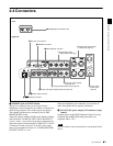
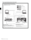
3 Analog video signal inputs/outputs
a VIDEO IN (analog video input) connector (BNC
type)
This inputs a composite video signal.
b VIDEO OUT 1, OUT 2 (SUPER) (analog video
output 1, output 2 (superimpose)) connector (BNC
type)
These output composite video signals.
The output from the VIDEO OUT 2 (SUPER) connector
can have time code, menu settings, alarm messages, and
other text information superimposed.
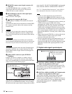
4 SDI signal inputs/outputs
a SDI IN (SDI signal input) connector (BNC type)
This inputs an SDI format video/audio signal.
b SDI OUT (SUPER) (SDI signal output
(superimpose)) connector (BNC type)
This outputs an SDI format video/audio signal.
When the unit is shipped from the factory, audio signal
output is 8 channels with no switching, and RP188 time
code output is set to on. You can change these settings with
extended menu item 828 “SDI/DV AUDIO OUTPUT
SELECT” and extended menu item 920 “SD-SDI H-ANC
CONTROL.”
The output can have time code, menu settings, alarm
messages, and other text information superimposed. To
turn superimposition off, set the maintenance menu item
“OTHERS”-“SDI SUPER” to “OFF.”
To treat the input and output signals of these connectors as
non-audio signals, set the maintenance menu item
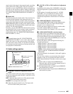
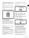
AUDIO OUT
1/3 2/4
1/3 2/4
AUDIO IN
1 AUDIO IN 1/3, 2/4 connectors
2 AUDIO OUT 1/3, 2/4 connectors
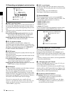
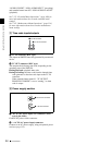
VIDEO
IN OUT1 OUT2(SUPER)
1 VIDEO IN connector
2VIDEO OUT 1, OUT 2
(SUPER) connectors
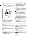
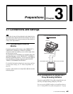
SDI
IN OUT(SUPER)
1 SDI IN connector
2SDI OUT (SUPER)
connector