


Chapter 7 Menus
106
7-3 Extended Menu
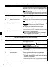
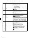
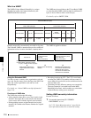
731 WIDE MODE Specify whether to record and play back with the addition of wide picture
information.
Sub-item
1 INPUT Specify whether to save wide picture information on a disc during recording.
auto
: Automatically record wide picture information when it is detected in the
selected input video signal.
on: Always record wide picture information.
off: Do not record wide picture information.
2 OUTPUT Specify whether to add wide picture information to the output signal during
MPEG IMX playback.
thru (through)
: Output the video signals of the disc being played back
without adding wide picture information.
auto: When wide picture information is detected on the disc being played
back, add wide picture information to the output video signals.
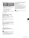
Notes
• To add wide picture information to the output signal, it is necessary, in
addition to setting this item to “thru,” to operate extended menu item 703 to
set line 20 (in 525 line mode) to “thru” or set line 23 (in 625 line mode) to
“thru.”
• In 525 line mode, wide picture information may not be output if VITC signal
insertion position is set to line 20 in extended menu item 601 or 602.
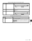
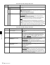
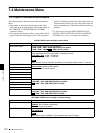
Menu items in the 700s, relating to video control
Item
number
Item name Settings
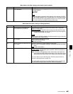
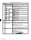
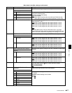
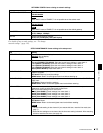
Menu items in the 800s, relating to audio control
Item number Item name Settings
802 DIGITAL AUDIO MUTING IN
SHUTTLE MODE
Set the audio muting conditions during shuttle playback.
off
: Not muted.
on: Muted.
807 AUDIO OUTPUT PHASE Set the output timing of digital audio playback signals (SDI, AES/EBU
only), with 80H as a reference position. Output timing is earlier for
values smaller than 80H and later for values greater than 80H. (80H,
128 samples = approx. 2.7 ms, 80H, 1 sample = approx. 20 μs)
0 (0 (HEX))... 80 (80 (HEX))
... FF (FF (HEX)): Values can be set in this
range.
808 INTERNAL AUDIO SIGNAL
GENERATOR
Select the operation of the internal audio test signal generator.
silnc (silence): Silent signal.
1kHz (1kHz sine)
: 1 kHz, –20 dB FS sine wave signal.
When you select SG as the audio input in the input selection section of
the control panel, the audio test signal generated by the internal audio
test signal generator is input.
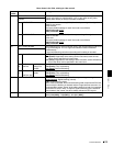
815 AUDIO SAMPLING RATE
CONVERTER
Select the mode of operation of the sampling rate converter for AES/
EBU input to channels 1 to 4.
off
: Do not operate.
on: Operate.
820 AUDIO OUTPUT CH1/CH2 SELECT Select the signals to be output from the AUDIO OUT 1/3 and AUDIO
OUT 2/4 connectors.
line (line out)
: Output the audio channel signals selected with item 824
“just as they are” from the AUDIO OUT 1/3 and 2/4 connectors.
moni (monitor out): Output the monitor audio L-channel (CH-1) and
monitor audio R-channel (CH-2) signals from the AUDIO OUT 1/3 and
AUDIO OUT 2/4 connectors, respectively.