


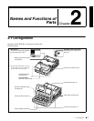
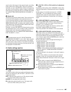

Chapter 2 Names and Functions of Parts
19
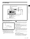
2-3 LCD Panel
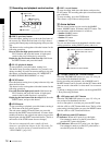
“BATT” and “E” flashing: Exhausted (charging
required). Operation of the PDW-R1 stops.
e Disc loaded mark
This lights while a disc is loaded in the PDW-R1. It flashes
as the disc is inserted, and while it is being ejected.
2 Audio and video settings section
a AUDIO INPUT CH (channel) button
This selects the channel to which the audio input signal
selection applies.
Each press of this button selects the next audio input
channel, in the following order.
CH1 t CH2 t CH3 t CH4
The selected channel appears in the time data display and
video panel.
You can use the AUDIO INPUT SEL button to select the
audio input signal for the selected channel.
When audio is in eight-channel mode
On channels 5 to 8, you can input only the audio signals
embedded in an SDI signal.
b AUDIO INPUT SEL (selection) button
This selects the input signal to the channel selected with
the AUDIO INPUT CH button described above.
Each press of this button selects the next audio input
signal, and the audio input indications in the time data
display and video panel change to reflect this.
ANALOG: Analog audio signal input to the AUDIO IN
connector
SDI: SDI audio signal input to the SDI IN connector
AES/EBU: AES/EBU format digital audio signal input to
the DIGITAL AUDIO (AES/EBU) IN connector
SG: Audio test signal generated by the internal signal
generator
c VIDEO INPUT SEL (selection) button
Pressing this button cycles through the following
selections of the video input signal.
• SDI video signal input to the SDI IN connector
• Composite video signal input to the VIDEO IN
connector
• Test video signal from the internal signal generator
• i.LINK-compliant DVCAM format digital signal
(i.LINK input comprising both video and audio signals)
input to the S400 (i.LINK) connector
Signals are selected in the following order. The video input
indication in the video panel changes to reflect this.
SDI t COMPOSITE t SG t i.LINK
Note
Input signals (AV/C) from the S400 (i.LINK) connector
cannot be recorded when the basic menu item 031
“RECORDING FORMAT” is set to “IMX 50,” “IMX40,”
or “IMX 30.” E-E video display and audio output are also
not possible.
Select a signal other than “i.LINK” to record IMX format
video signals. When i.LINK input signals are selected, set
basic menu item 031“RECORDING FORMAT” to
“DVCAM.”
See 7-2-2 “Basic Menu Operations” (page 94) for more
information about how to make basic menu settings.
3 Display settings section
a STATUS button
Displays information about the current settings of this unit
in the video panel.
The displayed information changes in the following order
with each press of the button.
Page 1 t Page 2 t Display off
Items displayed on page 1
AUDIO
VIDEO
INPUT SEL
WARNING
KEY INHI RE
INPUT CH INPUT SEL
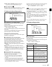
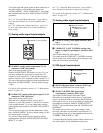
1 AUDIO INPUT CH button
3 VIDEO INPUT SEL button
2 AUDIO INPUT SEL button
Item Description
525, 625 Line mode selected with basic menu
item 013
IMX50, IMX40,
IMX30, DVCAM
Video recording format selected with
basic menu item 031
8ch, 4ch Number of audio recording channels
(When the format is IMX50/40/30, this
is the number of channels specified by
maintenance menu item “AUDIO
CONFIG” - “DATA LENGTH.” When the
format is DVCAM, this is always 4ch.)
VIN The video input signal selected with the
VIDEO INPUT SEL button (setting
values: SDI, COMPST, SG, i.LINK)
AINn (n: channel
number 1 to 4)
The audio input signal selected with the
AUDIO INPUT SEL button (setting
values: SDI, AES/EBU, SG, ANALOG)
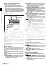
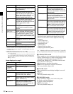
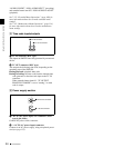
REC INHI
STATUS CHARACTER LIGHT MONITOR
HLOFFOFF ON
OFF ON
PROCESS
CONTROL
1 STATUS button
3 LIGHT switch
2 CHARACTER switch
4 MONITOR switch