Glossary
158
Technical Services Group ~ 1-800-283-5936 (USA) ~ 1-801-974-3760
Reverberation
A diffused acoustic energy field fed and maintained by sound
reflections from the room surfaces.
S–Z buses
These eight buses are defaulted as auxiliary mix buses. They are used to
route auxiliary audio to and from other units on the network. These buses are also
used as mic mix buses when NOM count is not required.
Serial Command
A bit description designed to execute an instruction or command.
Serial mode The serial mode determines the format in which serial commands
return—text or binary. The mode defaults to Binary when G-Ware is connected
and to Text when disconnected. Contact technical support for instructions on using
Binary mode.
Signal Delay
Used for:
• Compensating for physical placement of multiple drivers in a cluster—to
align points of acoustic origin in the same plane.
• Ensure matching arrival times at listeners from multiple loudspeaker
drivers.
• Using the Haas effect to maintain localization of the source, even with a
distributed system.
Signal Generator
A device for generating a reference tone for sound system
calibration purposes.
Site file
A site file is a file created by G-Ware which is saved on your computer.
The site file contains all information about a particular installation including all unit
settings and properties. It also provides G-Ware with the necessary informaiton to
communicate with the site hardware using your PC.
Site properties
The Site Properties window opens when you select New Site from
the File menu or click on the New Site button on the toolbar. It allows you to enter
information about the site as well as configure the communication and security
settings.
Speech Leveler
Essentially an AGC applied to a speech signal after processing by
a noise cancellation stage. Acts only on voice signals. Does not pull up the noise floor
during periods of no signal.
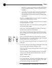
Table View
Displays the numerical values of the filter parameters for all nodes of
the active filter display.
TERL
The telco echo return loss (TERL) meter shows the coupling between the
transmit signal and the input to the telephone echo canceller. It is the ratio of the
two levels.


