


Introduction ~ Controls and Connections
5
Technical Services Group ~ 1-800-283-5936 (USA) ~ 1-801-974-3760
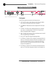
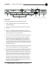
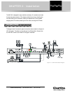
Rear panel
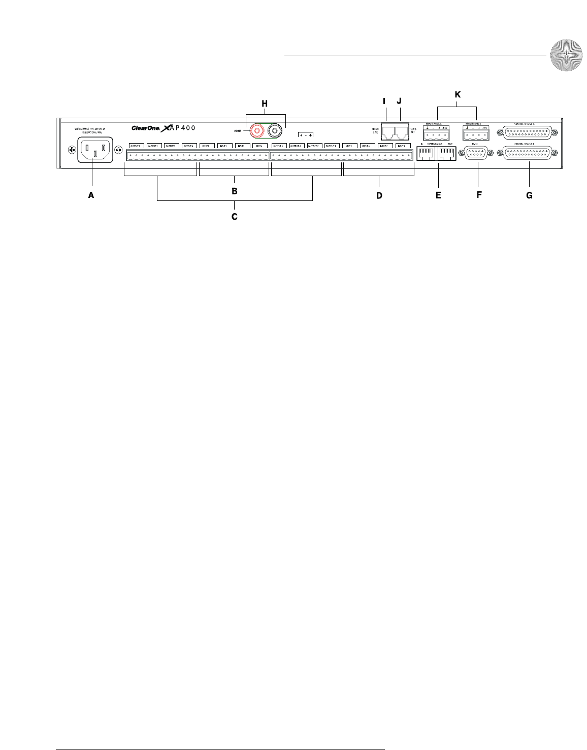
The XAP 400 rear-panel connectors perform the following functions:
A. Power. The AC power cord input is a IEC type connector allowing
100–240VAC, 50/60Hz.
B. Inputs 1–4. These Phoenix-type connection blocks are for mic and/or line
level inputs.
C. Outputs 1–8. These Phoenix-type connection blocks are for line level
outputs that may be configured for any combination of gated and non-gated
inputs, as well as a mix of mic and line level inputs.
D. Inputs 5–8. These Phoenix-type connection blocks are for line level inputs.
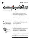
E. Expansion Bus In, Out. This RJ-45 connector is used to connect XAP
units. G-Ware is capable of accessing and controlling an expansion bus
network of up to eight XAP 400/800/PSR1212 units and 16 XAP TH2
units, where the total number of microphone inputs does not exceed 64. The
expansion bus supports a distance of up to 80 feet between each connected
XAP 400/800 or PSR1212.
F. RS-232. This female DB9 serial port connects the XAP 400 to a PC, modem,
or other custom remote controller. For serial commands, see page 102.
G. Control/Status Ports A and B. These two female DB25 connectors are for
general purpose input/output (GPIO) control of custom or unique control
devices. The control devices access the command set for the XAP 400 and
can be used for common functions such as volume control, muting, preset
changes, room combining, etc. Devices can be connected to either port.
For instructions on how to program the control and status pins, see the
GPIO section on page 85. The default settings allow control and status of
inputs, outputs, volume, and presets. These pins are active low. For pinout
and default information, see Appendix B.
Figure 1.3. XAP 400 rear-panel connectors