


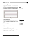

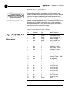
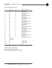
Control/Status A Port Pinout (female)
Pin Definable Type Default Description
1 Yes Control Lock front panel toggle
2 Yes Status Status of front panel lock
3 Yes Control Mute all mics toggle
4 Yes Status Status of mute all mics
5 Yes C Mute Output 9 toggle
6 Yes S Status of Output 9 mute
7 Yes C Mute Output 10 toggle
8 Yes S Status of Output 10 mute
9 Yes C Mute Output 11 toggle
10 Yes S Status of Output 11 mute
11 Yes C Mute Output 12 toggle
12 Yes S Status of Output 12 mute
13 Yes C Volume Up D Output 1 (1dB)
14 Yes S Not programmed
15 Yes C Volume Down D Output 1 (1dB)
16 Yes S Not programmed
17 No S Mic #1 Gate Status
18 No S Mic #2 Gate Status
19 No S Mic #3 Gate Status
20 No S Mic #4 Gate Status
21 No S Mic #5 Gate Status
22 No S Mic #6 Gate Status
23 No S Mic #7 Gate Status
24 No S Mic #8 Gate Status
25 No Ground Ground
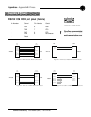
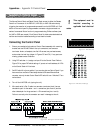
13
25
1
14
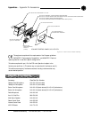
Figure B.6. Control/Status Ports A, B
Control/Status connectors
The Control/Status connections are provided on two DB-25 connectors. These
connectors are labeled Control/Status A and Control/Status B and contain different
types of pins. The inputs on these connectors are internally pulled high and are
activated by connecting the pin to ground. The outputs are open collectors, which are
open when inactive and grounded when active. This allows the XAP 400 to control
and be controlled by a wide variety of external devices, including relays, lamps,
switches, and other equipment. Control pins on Control/Status A are momentary
while control pins on Control/Status B are latching.
Appendices ~ Appendix B: Pinouts
96
Technical Services Group ~ 1-800-283-5936 (USA) ~ 1-801-974-3760
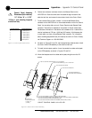
The first 16 pins on the
Control/Status Port A can
be programmed using
G-Ware software.
✍