


Connecting Other Sources
27
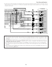
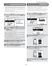
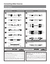
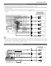
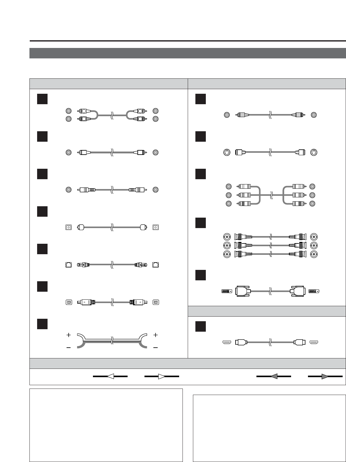
Cable indications
Signal direction
Audio and Video cable
• The hookup diagrams on the subsequent pages assume the use of the following optional connection cables (not supplied).
Video cableAudio cable
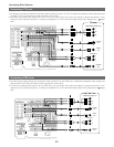
NOTE:
• Do not plug in the power supply cord until all connections
have been completed.
• When making connections, also refer to the operating
instructions of the other components.
• Be sure to connect the left and right channels properly
(left with left, right with right).
• Note that binding pin-plug cables together with power
supply cords or placing them near a power transformer
will result in generating hum or other noise.
Analog connections (Stereo)
A
R
L
R
L
(Orange)
(Green)
(Blue)
(Red)
Pin-plug cable
Analog connections (Monaural, for subwoofer)
B
Pin-plug cable
Digital connections (Coaxial)
C
Coaxial cable (75 Ω/ohms pin-plug cable)
Digital connections (Optical)
D
Optical cable (Optical fiber cable)
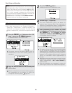
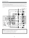
DENON LINK connections
E
DENON LINK cable
IEEE1394 connections
F
4-pin, S400 IEEE1394 cable
Speaker connections
G
Speaker cable
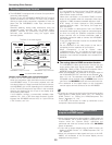
Video connections
H
Video cable (75 Ω/ohms video pin-plug cable)
S-Video connections
I
S-Video cable
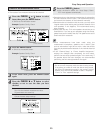
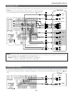
Component video connections
J
Component video cable
DVI-D connections
L
24-pin DVI-D cable
HDMI connections
M
19-pin HDMI cable
(Yellow)
Audio signal Video signal
(Y)
(P
B
/C
B
)
(P
R
/C
R
)
IN OUT OUT ININ OUT OUT IN
(White)
(Red)
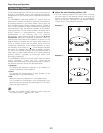
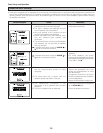
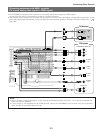
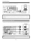
NOTE:
• Connecting a LD (laser disc) player with a Dolby
Digital RF Output
The AVR-5805CI does not have a DD RF demodulator
function. Therefore, you need to use a commercially
available outboard DD RF demodulator and connect its
digital output to one of the AVR-5805CI available digital
inputs. Refer to the demodulator’s operating instruction
for further information.
Component video connections
K
BNC (75 Ω/ohms) cable
(Y)
(P
B
/C
B
)
(P
R
/C
R
)
(Y)
(P
B
/C
B
)
(P
R
/C
R
)