


22 LED-PRO • User’s Guide
3. Installation
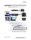
Signal Installation
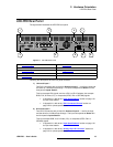
~ If you are using RS-232 communications, connect the laptop to LED-
PRO’s RS-232 Port.
~ If you are using Ethernet communications, a totally “local” network is
recommended, without IP connections to the outside world:
• Use a crossover Ethernet cable for a direct connection, or
• Use a standard Ethernet cables in conjunction with an Ethernet
hub or switch.
3. Ensure that your LED wall is properly assembled, and that all data cables are
connected to all tiles — in the proper sequence. Refer to your specific LED tile’s
“User’s Guide” for details.
4. Connect LED-PRO’s LED Interface output to the data input of your LED wall.
Please note:
~ Use the proper cable, depending upon your LED wall’s input connector
(e.g., DVI or MDR). Refer to the “Cable and Adapter Information” on
page 18 for details on all connection cables.
~ (Option) If you are using a fiber optic link:
• Ensure that power is properly connected to all Fiberlink units.
• Connect LED-PRO’s LED Interface output to the input of the
Fiberlink Transmitter.
• Connect a fiber optic cable from the output of the Fiberlink
Transmitter to the input of the Fiberlink Receiver.
• Connect the output of the Fiberlink Receiver to the data input of
your LED wall.
5. (Option) If you are using the Barco AEC:
~ Ensure that power is properly connected to the AEC.
~ Connect the data output of your LED wall to the input of the AEC.
Please continue with system setup, menu orientation and operations, as outlined in
Chapter 4, “Operation” on page 25.
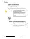
Note
A 15 meter RS-232 cable is provided, which will assist you in
viewing the LED wall while simultaneously using your laptop
for calibration purposes.