


16 LED-PRO • User’s Guide
2. Hardware Orientation
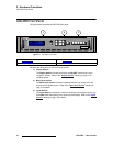
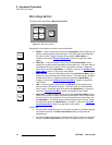
LED-PRO Rear Panel
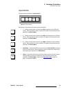
3) Universal Input 3
Five BNC connectors are provided for Universal Input 3 — each with a buffered
loop-through. The input corresponds to Button 3 in the Inputs Section, and
accepts RGB, YUV, S-Video (Y/C), or composite (NTSC, PAL or SECAM) signals.
~ In Appendix A, refer to the “Input Specifications” section on page 118
for input video details.
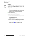
4) SDI Input
One BNC connector is provided for the SDI Input. The input corresponds to the
SD/HD SDI button in the Inputs Section, and accepts SD-SDI or HD-SDI signals.
~ In Appendix A, refer to the “Input Specifications” section on page 118
for input video details.
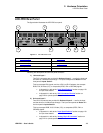
5) LED Interface
One DVI-I connector is provided for the system’s output to an LED wall. The
output is digital only.
~ In Appendix A, refer to the “Output Specifications” section on page 119
for output video details.
~ In Appendix A, refer to the “DVI-I Connector Pinouts” section on
page 122 for pinout specifications.
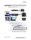
6) Ethernet Port
One RJ-45 connector is provided for 10/100BaseT Ethernet communications with
LED-PRO.
~ The port is typically used for diagnostics, or command-line operations via
Telnet.
~ Telnet is via port 10001.
S telnet 192.168.1.100 10001
In Appendix A, refer to the “Ethernet Connector
” section on page 123 for
pinouts.
7) RS-232 Port
One 9-pin D connector is provided for RS-232 serial communications with LED-
PRO. The port is typically used for communications with Barco’s Director
Toolset Graphical User Interface (GUI).
In Appendix A, refer to the “Serial and Diagnostic Connector” section on
page 124 for pinouts.
8) Diagnostics Port
One 9-pin D connector is provided for RS-232 serial communications with LED-
PRO. Similar to the Ethernet port, this port is typically used for diagnostics,
uploading code or command-line operations via HyperTerminal or the Flash
Loader.
In Chapter 4, refer to the “Diagnostic RS232
” section on page 88 for port setup
operations. In Appendix A, refer to the “Serial and Diagnostic Connector”
section on page 124 for pinouts.
9) AC Connector
One AC Connector is provided for connecting LED-PRO to your facility’s AC
power source. The integral switch turns the chassis on and off.