


LED-PRO • User’s Guide 15
2. Hardware Orientation
LED-PRO Rear Panel
ibaJmol=oÉ~ê=m~åÉä
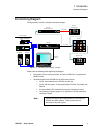
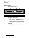
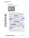
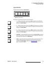
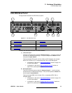
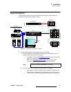
The figure below illustrates the LED-PRO rear panel:
Figure 2-1. LED-PRO Rear Panel
Following are descriptions of each rear panel connector:
1) Universal Input 1
Two DVI-I connectors are provided for Universal Input 1 — one for the input and
the other for a buffered loop-through. The input corresponds to Button 1 in the
front panel’s Inputs Section.
This input accepts DVI signals, and via a DVI-I to HD-15 adaptor, also accepts
RGB, YUV, S-Video (Y/C), or composite (NTSC, PAL or SECAM) signals.
~ In Appendix A, refer to the “Input Specifications” section on page 118
for input video details.
~ In Appendix A, refer to the “DVI-I Connector Pinouts” section on
page 122 for pinout specifications.
2) Universal Input 2
Two HD-15 connectors are provided for Universal Input 2 — one for the input
and the other for a buffered loop-through. The input corresponds to Button 2 in
the front panel’s Inputs Section.
This input accepts RGB, YUV, S-Video (Y/C), or composite (NTSC, PAL or
SECAM) signals.
~ In Appendix A, refer to the “Input Specifications” section on page 118
for input video details.
~ In Appendix A, refer to the “Analog 15-pin D Connector” section on
page 121 for pinout specifications.
RS-232
DIAGNOSTICSETHERNET
100-240 V 50-60 Hz
2.3 A
LED INTERFACE
SDI INPUT
UNIVERSAL INPUT 1
IN LOOP
UNIVERSAL INPUT 2
IN LOOP
UNIVERSAL INPUT 3
LOOP
IN
R/R- Y/C
R/R- Y/C
LOOP
IN
G/Y/COMPOSITE
G/Y/COMPOSITE
LOOP
IN
B/B-Y
B/B-Y
LOOP
IN
H/C
H/C
LOOP
IN
V
V
4
1
2
3 5 7
986
1) Universal Input 1 6) Ethernet Port
2) Universal Input 2 7) RS-232 Port
3) Universal Input 3 8) Diagnostics Port
4) SDI Input 9) AC Connector
5) LED Interface