


124 LED-PRO • User’s Guide
^K==péÉÅáÑáÅ~íáçåë
Pinouts
pÉêá~ä=~åÇ=aá~ÖåçëíáÅ=`çååÉÅíçê
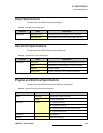
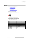
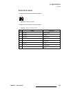
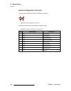
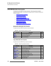
The figure below illustrates the Serial and Diagnostic connector:
Figure A-4. Serial and Diagnostic Connector
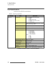
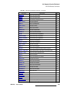
The table below lists Serial and Diagnostic connector pinouts.
Table A-10. Serial and Diagnostic Connector Pinouts
Pin RS-232 Signal Description
1 CD Carrier Detect
2 RXD Received Data
3 TXD Transmitted Data
4 DTR Data Terminal Ready
5 GND Signal Ground
6 DSR Data Set Ready
7 RTS Request To Send
8 CTS Clear To Send
9 RI Unused
51
96