


LED-PRO • User’s Guide 13
2. Hardware Orientation
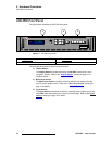
LED-PRO Front Panel
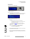
fåéìíë=pÉÅíáçå
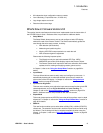
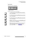
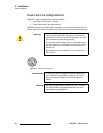
The figure below illustrates the Inputs Section:
Figure 2-5. Inputs Section
Descriptions of each button and control are provided below:
• 1 — selects universal input 1 (the rear panel DVI connector) as the LED wall’s
source. When pressed, the input is routed to the output using the transition type
specified in the Effects Menu.
• 2 — selects universal input 2 (the rear panel HD-15 connector) as the LED wall’s
source. When pressed, the input is routed to the output using the transition type
specified in the Effects Menu.
• 3 — selects universal input 3 (the rear panel BNC connectors) as the LED wall’s
source. When pressed, the input is routed to the output using the transition type
specified in the Effects Menu.
• SD/HD SDI — selects the SD/HD input (the rear panel SDI Input BNC connector)
as the LED wall’s source. When pressed, the input is routed to the output using
the transition type specified in the Effects Menu.
• LOGO — selects the LOGO (as stored in flash memory) as the LED wall’s source.
When pressed, the LOGO is routed to the output using the transition type
specified in the Effects Menu. Refer to the “About the LOGO
” section on
page 14 for additional details.
1 2 3
SD/HD
SDI
LOGO
INPUTS
1
2
3
SD/HD
SDI
LOGO