


LED-PRO • User’s Guide 21
3. Installation
Signal Installation
páÖå~ä=fåëí~ää~íáçå
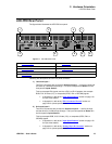
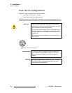
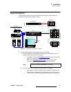
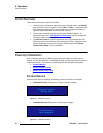
The figure below illustrates a sample LED-PRO system diagram. Use this figure for
reference during the signal installation process.
Figure 3-2. LED-PRO System Diagram (sample)
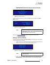
Use the following steps to install signals to/from the LED-PRO:
1. Connect outputs from your selected source devices to LED-PRO’s inputs. A
maximum of four devices can be connected.
~ In Chapter 2, refer to the “LED-PRO Rear Panel” section on page 15 for
details on all rear panel universal input connectors.
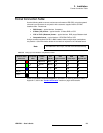
~ Refer to the “Format Connection Table” section on page 23 for
connection details using a customer supplied breakout cable.
2. Connect a laptop PC to LED-PRO via either RS-232 or Ethernet.
~ Ensure that the Director Toolset is properly installed on the laptop PC.
~ Director Toolset is required for LED wall calibration, but it is not required
for initial setup. LED-PRO’s “Setup Wizard” is used for this purpose.
Laptop PC (Director Toolset)
LED-PRO
LED Wall
(Optional)
Fiberlink Transmitter
(Optional)
Fiberlink Receiver
(Optional) AEC
PC (DVI)
Camera (Composite)
DVR (SDI)
PC (RGB)
Ethernet or
RS-232
Fiber Optics
DVI (Direct)
Up to 4 Inputs
Note
All inputs except the SDI Input can be looped.