


LED-PRO • User’s Guide 7
NK==fåíêçÇìÅíáçå
Connectivity Diagram
`çååÉÅíáîáíó=aá~Öê~ã
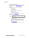
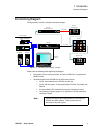
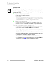
The figure below provides a sample connectivity diagram:
Figure 1-1. LED-PRO System Diagram (sample)
Please note the following points regarding the diagram:
• The maximum of four inputs are shown, one each in RGB, DVI, Composite and
HD-SDI formats.
• Two different paths from LED-PRO to the LED wall are shown:
~ Via DVI, direct between the LED-PRO and the wall.
~ Via DVI and fiber optics, via the optional Barco Fiberlink Transmitter and
Receiver.
~ An optional Barco AEC (Ambient Environment Controller) is shown.
~ The (customer supplied) laptop PC is required for LED wall calibration,
via Director Toolset.
Laptop PC (Director Toolset)
LED-PRO
LED Wall
(Optional)
Fiberlink Transmitter
(Optional)
Fiberlink Receiver
(Optional) AEC
PC (DVI)
Camera (Composite)
DVR (SDI)
PC (RGB)
Ethernet or
RS-232
Fiber Optics
DVI (Direct)
Up to 4 Inputs
Note
Contact your Barco sales representative for information on
Fiberlink and AEC systems. These products are not
discussed in this user’s guide.