


Installation and Setup
38
Instruction Manual – HDMI-UTPRO-0808
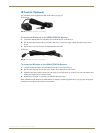
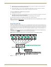
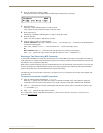
RS-01 Adapter Cable (FG-RS01)
The adapter cable can be ordered by itself for a DCE interface with female connection.
Serial port as DCE interface with female connection:
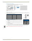
Serial Port (RJ-12) Pinout
The following table provides the pinout configuration for the RJ-12 connector (Serial port) on the HDMI-UTPRO-0808
and also on the HDMI-UTPRO-RX Receiver.
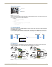
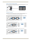
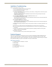
To connect an external serial device:
1.
Plug the RJ-12 end of the adapter cable into the Serial port on the HDMI UTPro
(or Receiver).
2. As needed – Connect cable adapter(s) per the desired Cable Kit option on the
previous page.
3. Plug the DB-9 end of the adapter cable (or the end cable adapter) into the serial
port on the external device.
4. Check to be sure that the device’s serial port settings and serial port settings on the enclosure (see table to the right)
correspond to each other. If necessary, the default settings on the HDMI UTPro can be changed; see page 87.
FIG. 26 DCE interface with female connection
RX RJ-12 Pinout
Function Abbreviation RJ-12 Connector
Data Set Ready DSR Pin 1
Transmit Data TD or TX or TXD Pin 2
Receive Data RD or RX or RXD Pin 3
Signal Ground GND Pin 4
Signal Ground GND Pin 5
Data Terminal Ready DTR Pin 6
DB-9 Serial Port Pinouts
(female connector)
RS-232
Pin 2: TX signal
Pin 3: RX signal
Pin 5: GND
Female
HDMI UTPro
RJ-12 Port Settings
Baud Rate 9600
Data Bits 8
Parity None
Stop Bits 1
Flow Control None
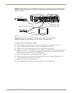
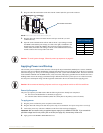
Caution: To avoid system damage, follow the power-up sequence on page 40.
Serial Port (RJ-12) Pinout