


Appendix A – EDID Programmer
104
Instruction Manual – HDMI-UTPRO-0808
2. Connect an HDMI cable to the PC using the PC’s spare monitor port (if your PC has a DVI port, use a
DVI-to-HDMI cable adapter).
3. Connect the open end of the HDMI cable to the destination device (typically a monitor) from which the EDID
information needs to be read.
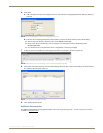
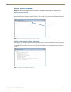
4. Click the Refresh Display List button to update the Available Displays drop down list.
5. From the Available Displays drop down list, select the destination device from which you need to read the EDID.
6. Click the Read button to read the EDID information. The results display in the read-only area.
7. Click the Save button (select location, enter file name, and click Save).
Leave the EDID Programmer open for instructions on writing the EDID to the HDMI input (see the following
section).
8. Disconnect the HDMI cable from the PC and from the destination device.
Using Cable Adapters
Cable adapters may be needed depending on the type of ports available on the PC.
If the PC has a DVI port – from the DVI port, attach a DVI cable; attach a DVI-to-HDMI cable adapter;
attach an HDMI cable; attach to the destination device. An HDMI-to-DVI cable adapter can also be used if
the available PC and destination device ports are reversed.
If the PC has an HD-15 port – from the HD-15 port, attach an HD-15 to DVI cable; attach a DVI to DVI
barrel; attach a DVI to HDMI cable; attach to the destination device.
Note: The EDID information is passed but not video signals.
Writing EDID Data to HDMI Matrix Switching Input Connector
To write EDID data to the EDID chip for an HDMI matrix switching input connector:
1.
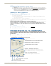
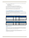
Attach a null modem serial cable without hardware flow control to the Control port (DB-9) on the HDMI UTPro.
Use a serial cable that matches the pin diagram in FIG. 68 for RS-232. The Control port uses pins 2, 3, and 5 only.
2. Attach the open end of the serial cable to the PC that the EDID Programmer will be opened on.
3. If necessary – From the Communication menu, select Change Settings to change the
baud rate for the PC’s serial port, which must match the baud rate for the HDMI UTPro.
The recommended (default) settings for serial communication with an HDMI UTPro are
in the table to the right.
4. Apply power to the enclosure.
5. On the PC, open the EDID Programmer.
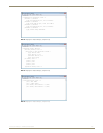
6. For the Target Device, select the Matrix Switcher option.
7. Click the Query AutoPatch Device button to obtain the XNNet address from the
enclosure.
8. Attach an HDMI cable to the PC using the PC’s spare monitor port (if your PC has a DVI or HD-15 port, see
“Using Cable Adapters” above).
9. Attach the open end of the HDMI cable to the HDMI matrix switching input connector that requires programming.
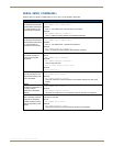
FIG. 68 RS-232 pinout
HDMI UTPro: DB-9PC: DB-9
HDMI UTPro
Serial Port Settings
Baud Rate 9600
Data Bits 8
Parity None
Stop Bits 1
Flow Control None