


Appendix D – Creating Virtual Matrices
119
Instruction Manual – HDMI-UTPRO-0808
Appendix D – Creating Virtual Matrices
Applicability Notice: This appendix applies to XNConnect version 2.10.0. XNConnect’s version information is found
under its Help menu.
Overview
The HDMI UTPro Matrix Switcher is pre-engineered at the factory. It is configured and ready to switch once the source
devices, receivers, and destination devices are attached.
The HDMI UTPro systems specify two identical virtual matrices for switching signals: VM 0 = All and VM 1 = Video.
These two VMs function the same for this product.
Creating new virtual matrices is an advanced feature of XNConnect. The configuration file does not need additional
virtual matrices unless you decide to use them to limit control of sources with limited sink support. If you decide to do
so, we strongly recommend contacting technical support to request a modified .xcl file or ask for assistance (for contact
information, see page 43).
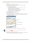
Important: If you find it necessary to modify the file for any reason, save a back up copy of the existing
configuration file. We also recommend providing technical support with a copy of the modified .xcl file for
future support.
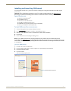
Example – Virtual Channels and Virtual Matrices
A system’s configuration allows incoming signals from source devices to be routed through the system and out to
destination devices.
For the HDMI UTPro, each virtual channel is assigned to a physical connector.
The virtual input and output channels can then be grouped into virtual matrices that define where the virtual channels can
be routed. A virtual channel on one VM cannot be routed to a virtual channel on another VM. For the HDMI UTPro, the
virtual channels are assigned to a VM in a sequential pattern.
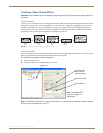
Note: Because a sequential pattern is used for creating VMs, the HDMI UTPro is easiest to configure if
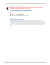
sources with the same sink limits are attached to adjacent connectors (FIG. 77).
The virtual matrices in the example used in this appendix assume no repeaters are used upstream or downstream of the
HDMI UTPro.
VM 1 – The sources connected to the inputs in orange (Inputs 1 through 6) each support 8 sinks and can be
routed to any or all of the outputs in orange on VM 1 (Outputs 1 through 8).
VM 2 – The source connected to the input in red (Input 7) supports only 4 sinks and can be routed to any or
all of the outputs in red on VM 2 (Outputs 1, 2, 3, and 4).
VM 3 – The source connected to the input in blue (Input 8) supports only 3 sinks and can be routed to any or
all of the outputs in blue on VM 3 (Outputs 5, 6, and 7).
Caution: Creating virtual matrices is an advanced feature of XNConnect that should not be attempted
unless you are extremely familiar with the program and the AMX Matrix Switcher being configured.
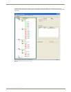
FIG. 77 Example of VMs created for control of sources with limited sink support
Example -
VM 2 (red)
VM 1 (orange)
VM 3 (blue)