


Installation and Setup
29
Instruction Manual – HDMI-UTPRO-0808
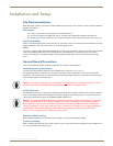
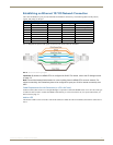
Important Twisted Pair Cable Recommendations
The requirements are the same for the twisted pair cable used with the ICS LAN 10/100 (Ethernet) connector and with
the DXLink (RJ-45) connector.
Twisted pair cable is designed to carry Full HD content over 100 meter (328 ft.) cables with control. For cable
specifications, see page 19. In a typical installation, the cables should be stretched to their full length between the
Transmitters and Receivers and the enclosure.
To keep from incurring video issues, the installation must use quality Cat5e, Cat6/6e, Cat6a, Cat7, SF/UTP,
S/FTP, or F/UTP cable. Do not use low skew cable or media twist category cable.
Twisted pair cable quality required in order to reach the 100 meter distance should meet ANSI/TIA/EIA
568A-5 or better specification and be rated for 250 MHz or better. For cable runs approaching the 100 meter
limit, Cat6/6e, Cat6a or Cat7 is recommended.
Do not use a tightly bundled or rolled cable.
Be sure to avoid kinks by following the manufacturer’s minimum bend radius.
Minimize service loops or coils whenever possible as they will reduce overall cable performance.
Transmission line performance can be impaired by the cable being placed in close proximity to electrically
noisy devices or other cables. Tight bundling of cables should be avoided in long run applications to reduce
crosstalk issues.
Cable end terminations should meet the TIA specification of the cable used to ensure optimal performance.
If running Cat5e or Cat6 cables together in a bundle, they can only be coupled for a distance of up to
60 meters before they must be separated over the remainder of the run. Cat6a and Cat7, which are shielded by
definition, can be bundled for the entire 100 meter run.
Important: DXLink twisted pair cable runs for DXLink equipment should only be run within a common
building.
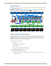
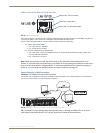
Attaching Cables for Switching/Transport
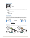
Top – HDMI Inputs and HDMI Outputs (Used for Matrix Switching)
The HDMI matrix switching inputs and outputs are on top and provide the system its switching capability. The 8 input
connectors are on the left side, and the 8 output connectors are on the right. The input and output connectors are
numbered separately. The source devices connect to the HDMI input connectors. The HDMI output connectors connect
to the HDMI input connectors on the bottom that are used for transport.
Note: If the installation requires only local destinations (not long cable runs), you can cable the HDMI matrix
switching outputs directly to the local devices. However, by using the transport connectors and included
Receivers, you gain the benefit of the NetLinx functionality of end point control which is included in the
HDMI UTPro's transport function. (Also note that short and long cable runs can be mixed-and-matched within
an installation.)
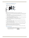
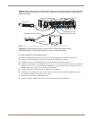
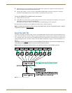
Bottom – HDMI Inputs and UTP Outputs (Used for Transport)
The 8 HDMI input and 8 UTP (RJ-45) output connectors used for transport are on the bottom and enable the system to
transport the HDMI signals over UTP cables. The HDMI matrix switching output connectors connect to the HDMI
transport input connectors. The UTP output connectors connect to the HDMI-UTPRO-RX Receivers, which in turn
connect to the destination devices.
Important: Do not
use a tightly bundled or rolled cable. In addition, minimize service loops or coils whenever
possible as they will reduce overall cable performance.