


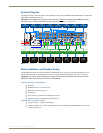

Installation and Setup
30
Instruction Manual – HDMI-UTPRO-0808
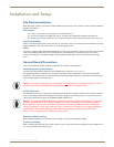
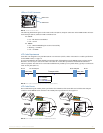
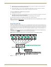
LEDs on RJ-45 Connectors
The following information applies to the LEDs on the UTP (RJ-45) transport connectors on the HDMI UTPro enclosure
and to the Input (RJ-45) connector LEDs on the Receivers.
Green:
On – link has been established
Off – no link
Yellow:
On – HDCP handshaking has occurred successfully
Blinking – no HDCP
Off – no HDMI
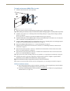
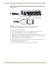
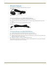
UTP Cable Requirements
UTP cable was designed to carry Full HD content over 100 meter (328 ft.) cables with control. For cable specifications
for the HDMI UTPro, see page 19.
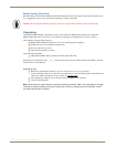
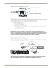
In a typical installation, the cables should be stretched to their full length between the HDMI UTPro enclosure and its
Receivers. Service loops or coils of the cable will reduce the overall cable performance and should be minimized
whenever possible. The total run of a UTP cable installation may include up to two patch cables, typically as connections
to RJ-45 wall jacks (FIG. 12).
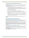
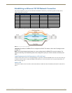
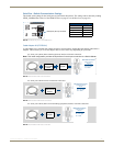
UTP Cable Pinouts
We recommend using the T568A pinout specification for termination of the UTP cable used with the UTP transport
connectors on the HDMI UTPro enclosure. The T568B pinout specification is also supported.
FIG. 11 RJ-45 connector LEDs
FIG. 12 UTP cable installation (only X and Z can be patch cables)
FIG. 13 UTP cable pinouts for T568A and T568B specifications
Green LED
Yellow LED
Patch cablePatch cable
RJ-45
RJ-45 wall jack
RJ-45
RJ-45 wall jack
Transport cable
X
Y
Z
Cable Length:
• X ≤ 5 meters
• Z ≤ 5 meters
• Y ≤ 100-X-Z meters