


43
sides of the listening position. The two
remaining speakers are referred to as
back surround speakers, as they are
placed in back of (behind) the listening
position. In 7.1-channel applications,
place
two of the surround speakers
in the
side positions, and place the two back
surround speakers on the rear wall.
In Dolby Digital and DTS systems, such as
JBL Cinema V
ision, it is best to aim all of
the speakers (except the subwoofer)
toward the listening position at about ear-
level height.
The low-frequency material reproduced by
the subwoofer is mostly omnidirectional,
and this speaker may be placed in a con-
venient location in the room. However
,
bass reproduction will be maximized when
the subwoofer is placed in a corner, along
the same wall as the front speakers.
Experiment with subwoofer placement by
temporarily placing the subwoofer in the
listening position and moving around the
room until the bass reproduction is best.
Place the subwoofer in that location.
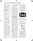
Step Two: Thanks to its sophisticated
video processor, the CVR700 is able to
upconvert composite, S-video and compo-
nent video source signals for a single-
cable connection to the screen. Connect
the included proprietary JBL Digital Link
™
cable to the Output to JBL Cinema
Vision CVPD50 Screen
on the back
of the CVR700, and to the digital input on
the underside of the CVPD50. The connec-
tor is located on the right side of the
screen when facing it. You may wish to
use a mirror to assist you in orienting the
cable connector correctly. Note that this
cable uses a proprietary system, and
should not be connected to any display
device other than the CVPD50.
The jack for the AC power cord is located
on the left side of the CVPD50. Make
sure the master power switch next to the
jack is in the “0” position before plugging
in the AC power cord. Again, a mirror
may be helpful in locating the jack and
switch. Do not turn the master power
switch to the “1” or on position until after
all components have been connected.
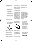
Step Three: Assemble the supplied
AM Loop Antenna so that the tabs at
the bottom of the antenna loop snap
into the holes in the base. Connect
it to the
AM
Antenna
T
erminals
.
Connect the supplied FM antenna to the
FM (75-ohm) Connection . The FM
antenna may be an external roof antenna,
an inside powered or wire-lead antenna
or a connection from a cable TV system.
If the antenna or connection uses 300-
ohm twin-lead cable, you must use an
optional 300-ohm-to-75-ohm adaptor to
make the connection.
If you would like to install any external
source devices in your system, proceed
to Step Four below
. Otherwise, you are
almost ready to begin enjoying your JBL
Cinema Vision home theater system.
Step Four:
Y
ou may wish to install addi-
tional components to your system. We re-
commend installing devices to the source
input jacks labeled for the corresponding
device type to benefit from both the pre-
assignment of digital audio inputs, and the
programming of the two remote controls.
Audio/video components require that
both an audio and a video connection be
made. The type of connection will depend
on the capabilities of your component.
Audio connections may be analog or digi-
tal. We recommend using digital audio
connections whenever possible for supe
-
rior sound reproduction. You may also
wish to make analog audio connections
as a backup.
Video connections for most devices may
be composite video (yellow jacks), S-
video (four-pin connector) or component
(Y/Pr/Pb – green, red and blue jacks)
video. Choose only one type of video
connection for each source component.
Whenever possible, we recommend using
component video connections for the best
quality. S-video provides an excellent
alternative, and composite video may be
used when neither S-video or component
video signals are available. As mentioned
above, the CVR700 will upconvert each
video format to the proper digital video
format for the CVPD50. However
, if you
are using another display device, you will
need to make a video monitor output con-
nection to the display corresponding to
each type of video format used by your
source components.
NOTES:
• The input source selectors and their
associated control codes on each of
the two remotes are preprogrammed to
operate only certain types of devices,
as listed below, although you may con-
nect any compatible audio/video device
to any of the inputs. Although you may
reprogram an input selector on the
main remote control so that its device
type matches the device you wish to
connect, the secondary remote’s input
selectors may not be reprogrammed.
Therefore, we recommend that you con-
nect compatible devices to each source.
Input
Device Types Preprogrammed
Source In Main Remote
AUX TV, HD Tuner, VCR/Combo,
DVD, CD, CABLE, SAT
VCR VCR/Combo
CBL/SAT CABLE, SAT, HD Tuner
GAME/ GAME, CAMCORDER
CAM
DR DVDR, CDR, DVHS, TIVO, PVR
DVI/ DVI/DVD, DVI/CABLE,
COMP DVI/SAT, HD Tuner
• The analog and digital audio connec-
tions, as well as the composite, S-
video and component video connec-
tions, are dedicated to each source
input as labeled and may not be reas-
signed to another source. Be certain to
make all of the connections for each
source device to the correct jacks.
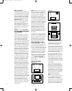
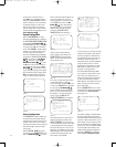
Cable/Satellite Source Input
Since the JBL Cinema Vision system does
not include a TV tuner, you may wish to
connect a cable TV box, satellite TV
receiver
, HDTV set-top tuner or another
device capable of receiving TV broad-
casts to the CVR700. This device should
be connected to the Cable/Sat source
input jacks. Select either the
Cable/
Satellite Coaxial Digital Audio Input
d or the Cable/Satellite Optical
Digital Audio Input
i for your digital
audio connection. If desired, connect the
analog audio outputs of the component
to the
Cable/Satellite Analog Audio
Inputs
‹. If available, connect the com-
ponent video outputs of your device to
the
Cable/Satellite Component Video
Inputs
°. Otherwise, connect either an
S-video or composite video output from
the component to the
Cable/Satellite
Analog V
ideo Inputs
‹.
NOTE
:
When using a source connected
via the
Cable/Satellite Component
Video Inputs
°, due to limitations in
the CVR700’s audio section, it is neces-
sary to also connect the corresponding
33
3
4
3
5
3
6
3
7
3
8
3
9
4
0
4
1
48
4
9
46
4
7
44
4
5
42
4
3
38
3
9
4
0
4
1
3
1
3
2
3
0
2
8
2
9
2
5
26
27
28
29
3
0
2
4
2
3
2
2
2
1
2
0
31
37
36
35
34
3
3
32
31
3
7
3
6
3
5
3
4
33
3
2
48
4
9
5
0
5
1
4
7
4
6
4
5
4
4
43
4
2
33
34
35
36
37
38
39
40
41
48
49
46
47
44
45
42
43
38
39
40
41
31
32
30
28
29
25
26
27
28
29
30
24
23
22
21
20
31
37
36
35
34
33
32
31
37
36
35
34
33
32
48
49
50
51
47
46
45
44
43
42
33
34
35
36
37
38
39
40
41
42
4
3
44
4
5
46
4
7
48
4
9
50
5
1
52
5
3
54
5
5
56
5
7
38
39
40
41
31
32
30
28
29
25
26
27
28
29
30
24
23
22
21
20
31
37
36
35
34
33
32
31
37
36
35
34
33
32
48
49
50
51
47
46
45
44
43
42
1 2 3 4 5
6
7
8 9 10 11 12
13 14 15 16 17 18
19 20 21 22 23 24
25 26 27 28 29 30
31 32 33 34 35 36
37 38 39 40 41 42
43 44 45 46 47 48
CVR700 OM 12/17/04 4:24 PM Page 43