


40
ance that matches that of the optional
CVTS50 speaker stands, the stand
includes a cradle for placement of the
center speaker.
IMPORTANT SAFETY NOTES:
• The credenza stand consists of three
main parts: two metal columns and a
glass base. Be extremely careful in
handling the fragile glass base to
avoid breakage that might result in
personal injury.
• The credenza stand is only intended for
use with the CVPD50 plasma screen.
Attempting to use the stand with any
other model plasma screen or any
other device is unsafe and may result
in personal injury and damage to the
equipment.
• The stand must be placed in a safe
location, protected from young children
and pets who might topple the stand,
possibly resulting in serious injury.
Never place the stand so that any part
of it is sticking out over the edge of
the credenza, table, shelf or other sur-
face underneath it.
• Make certain that your credenza or
other furniture is capable of supporting
the weight of the CVPD50 in a stable
fashion.
• If it becomes necessary to move the
CVPD50 to another location, two people
should carry it by holding the plasma
screen. Do not attempt to carry the
CVPD50 while holding it by the stand.
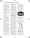
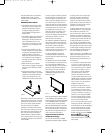
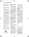
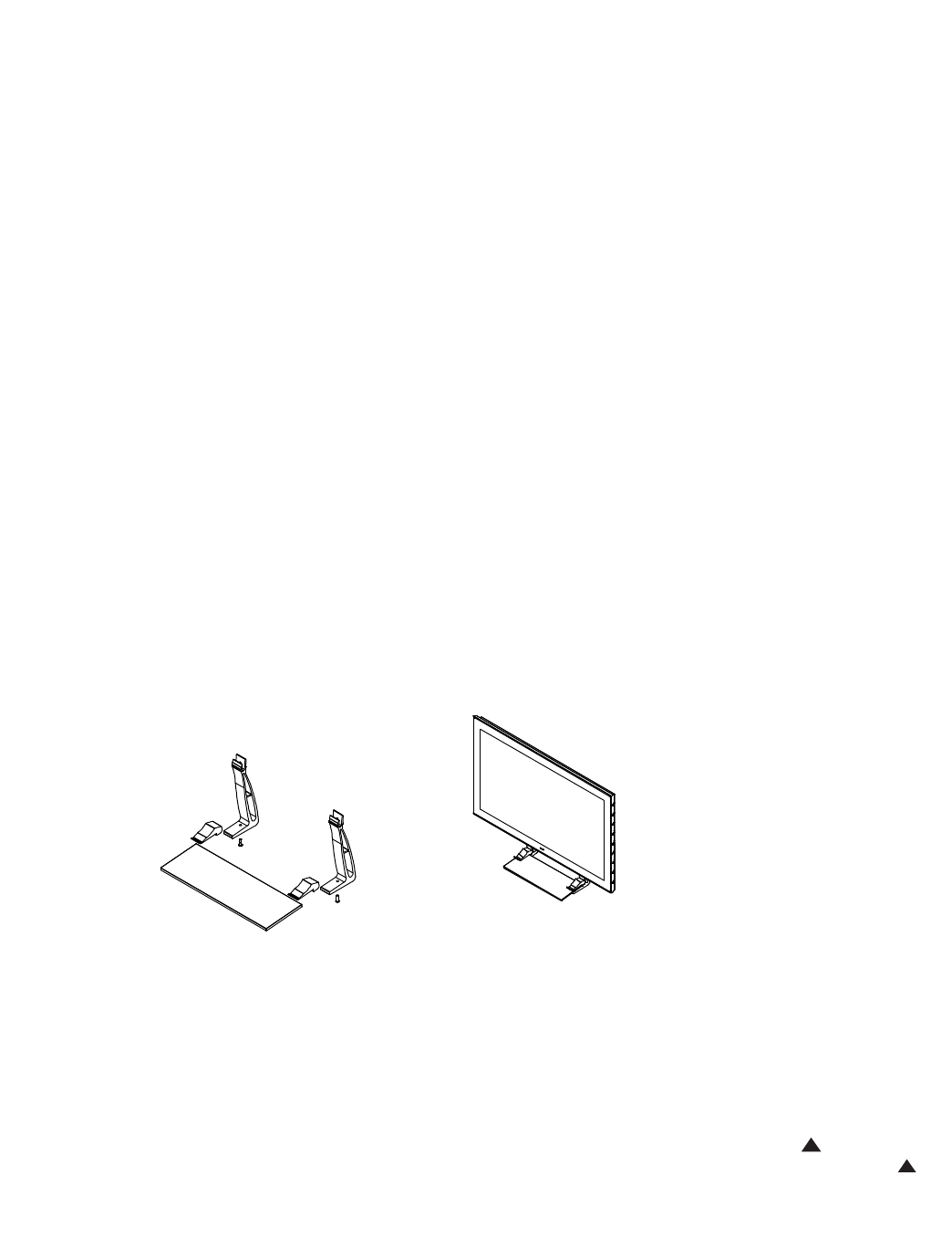
Figure 3
Each column is made up of two parts: the
main column and the top foot. Using the
supplied bolts, attach each foot to its col
-
umn, but do not fully tighten the bolts.
Use a 5mm hex key (not supplied).
Carefully insert the glass base into the
slot in the column, making sure to line up
each column flush with the edge of the
base. This will insure that the base is
installed evenly for maximum stability
and so that the columns will line up prop
-
erly with the openings on the underside
of the CVPD50.
To ensure a proper fit, GENTLY place the
plasma display on a carpeted floor with
one end up. Make sure that the screen
itself is at all times perpendicular to the
floor. While one person holds the unit
steady, the other person should check the
fit of each column in the two openings on
the underside of the unit. Loosen, move
and retighten the column feet until a
proper and secure fit is achieved. Then
secure the columns in their openings
using the two supplied hex bolts and the
same 5mm hex wrench you used to
attach the feet to the columns.
This method is preferable to placing the
stand on the credenza and lowering the
plasma display onto it, which may cause
the installers to place the display’
s
weight unevenly on the columns for a
moment, causing the glass base to snap,
which may result in personal injury.
It is the responsibility of the person
installing the display to properly and
securely mount the credenza stand to the
plasma display.
Two people may now right the CVPD50
and carefully place it in the desired loca-
tion.
Do not lean the CVPD50 on the
stand while righting it, as this will cause
the glass to snap, possibly resulting in
personal injury.
Carry the assembly by
holding the bottom and sides of the
CVPD50 plasma display itself,
not by
holding the stand.
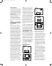
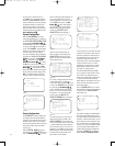
Figure 4
After the video cable has been connected
to the CVPD50 as described below, and
after the speaker wire has been connected
to the CVCEN50 speaker as described in
its owner’s manual, you may carefully
place the CVCEN50 speaker in the cradle
below the screen formed by the two top
feet of the credenza stand. The bottom of
the grille will fit snugly behind the two
stops at the front of the top feet.
Important Information About the
CVPD50 Plasma Display
Y
our new JBL Cinema Vision CVPD50
high-definition plasma display is capable
of opening a new world of video enjoy-
ment with sharpness and beauty far
beyond any television you have ever
owned. As this may be the first plasma
display device you have ever owned, it is
important to be aware of some unique
properties of this technology
.
A plasma display works by using a grid
containing millions of “cells”, each filled
with phosphorous that glows in red,
green or blue when it receives an electri
-
cal charge. The charge is supplied by a
wired grid that allows the video process-
ing logic to pinpoint each individual cell
to determine whether or not to turn it
“on”. The cells are sandwiched by glass
plates that seal the phosphorous in place.
The combination of cells, known as pixels
in video display terminology, when prop-
erly functioning can present a color pic-
ture with incredibly high resolution.
Given its construction, the CVPD50 is very
fragile, and requires extreme care in han-
dling. Once installed, it’s easy to use,
although there are a few points for you
to be aware of.
1. It is possible for a phenomenon known
as “burn-in” to occur when the phos-
phorous cells remain turned on for too
long a stretch of time. This is liable to
occur when a still image, such as a
menu screen or even the CVPD50’s
own start-up screen, remains on
screen for more than a few minutes.
In order to protect against burn-in, the
CVPD50’
s screen saver will be activated
after it detects 2 minutes of no move-
ment on screen. It is not possible to
disable the screen saver
.
However
, the screen saver does not
function for the DVI source. Therefore,
it is crucial that you set your source
device to activate its screen saver after
2 minutes of inactivity on screen, par
-
ticularly if you are using the CVPD50
with your computer, where an image
such as a spreadsheet may remain on
screen for a long period of time.
Burn-in is also of concern when you are
listening to audio CDs, which have no
visual information so that the CVPD50’s
start-up screen remains on. You may
wish to activate the Screen Standby
function, which places the screen in
standby mode, by pressing the Screen
Selector
e followed by the
Screen Standby Button Y .
Press the button again to restore the
video display
.
33
34
35
36
37
38
39
40
41
42
43
44
45
46
47
48
49
50
51
52
53
54
55
56
57
38
39
40
41
31
32
30
28
29
25
26
27
28
29
30
24
23
22
21
20
31
37
36
35
34
33
32
31
37
36
35
34
33
32
48
49
50
51
47
46
45
44
43
42
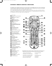
1 2 3 4 5
6
7
8 9 10 11 12
13 14 15 16 17 18
19 20 21 22 23 24
25 26 27 28 29 30
31 32 33 34 35 36
37 38 39 40 41 42
43 44 45 46 47 48
33
34
35
36
37
38
39
40
41
42
43
44
45
46
47
48
49
50
51
52
53
54
55
56
57
38
39
40
41
31
32
30
28
29
25
26
27
28
29
30
24
23
22
21
20
31
37
36
35
34
33
32
31
37
36
35
34
33
32
48
49
50
51
47
46
45
44
43
42
1 2 3 4 5
6
7
8 9 10 11 12
13 14 15 16 17 18
19 20 21 22 23 24
25 26 27 28 29 30
31 32 33 34 35 36
37 38 39 40 41 42
43 44 45 46 47 48
1238,8 1
754,8 1
950,1 3
515 1
1106,50
622
255,6 2
80,61 5
713,40 1
88,34 3
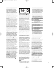
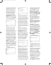
20-1/4"
5-1/2"
16"
17-3/4"
CVR700 OM 12/17/04 4:24 PM Page 40