


39
Before unpacking and placing the JBL
Cinema Vision components, it is impor-
tant to select appropriate locations for
each component. Make sure that all
power switches are turned off and all
equipment remains unplugged from AC
power until the system is completely
installed and connected in order to pre-
vent electric shock, or transient signals
that may damage equipment.
IMPORT
ANT NOTES:
•
Never attempt to lift the CVPD50 plasma
screen by yourself. Always make sure
an assistant is available to lift the plasma
screen with you.
• Do not block the ventilation holes of
the CVR700, and make sure that air can
circulate freely around it.
• Read through this manual before begin-
ning installation.
• Remember to observe the color coding
when connecting audio and video
cables.
Recommended Placement
The JBL Cinema Vision system will
provide the best results when installed
in a rectangular room, with the screen
installed on one of the shorter walls.
The front speakers should be placed the
same distance from each other as they
are from the listening position. They
should be placed at about the same
height from the floor as the listeners’
ears will be, or they may be angled
toward the listeners.
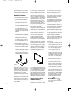
The center channel speaker should be
placed slightly behind the front left and
right speakers, and no more than 2 feet
above or below the tweeters of the left
and right speakers. This placement may
be obtained by placing the CVPD50
screen, and the left, right and center
speakers on a credenza using the included
pair of CVTS50 table stands for the left
and right CVSAT50 speakers, and the
included credenza stand for the CVPD50
screen and CVCEN50 center speaker.
The JBL Cinema V
ision speaker system
may be used in 5.1- or 7.1-channel appli-
cations. Y
our system includes enough
loudspeakers for a 5.1-channel system.
Additional pairs of CVSAT50 satellite
speakers are available from your JBL
dealer or custom installer
, along with
pairs of CVSAT50 table stands, should
you wish to upgrade to a 7.1-channel
system.
If desired, a second subwoofer may be
added to create a 5.2 or 7.2 system. If so,
connect one end of a Y-adaptor intercon-
nect to the
Subwoofer Output §, and
connect each end to the LFE input of a
powered subwoofer.
In 5.1-channel applications, two of the
surround speakers should be placed
slightly behind the listening position and,
ideally, should face each other and be at
a level higher than the listeners’ ears. If
that is not possible, they may be placed
on a wall behind the listening position,
facing forward. In 7.1-channel applica-
tions, place two of the surround speakers
in the side positions, and place the two
surround back speakers on the rear wall.
It is appropriate to configure the CVR700
for either 5.1- or 7.1-channel operation,
but not for 6.1 channels. When 6.1-chan-
nel program material or a 6.1-channel
processing mode is in use, material for
the surround back channel will be out-
putted simultaneously through both
the
Surround Back Left and Right
Speaker Outputs
¡. Connecting only
one loudspeaker to these speaker termi-
nals will not only deprive you of the bene-
fits of 7.1-channel surround modes, such
as Logic 7, but will also interfere with the
functioning of EzSet speaker calibration,
as described on page 51. It may also put
undesirable strain on the surround back
amplifier circuits and power supplies.
In Dolby Digital and DTS systems, it is
best to aim all of the speakers (except the
subwoofer) toward the listening position
at about ear-level height. The low-fre-
quency material reproduced by the sub-
woofer is mostly omnidirectional, and this
speaker may be placed in a convenient
location in the room. However
, bass
reproduction will be maximized when the
subwoofer is placed in a corner along
the same wall as the front speakers.
Experiment with subwoofer placement by
temporarily placing the subwoofer in the
listening position and moving around the
room until the bass reproduction is best.
Place the subwoofer in that location.
Wall-Mounting the CVPD50 Plasma
Display
Due to its weight and fragility, there are
special concerns in wall-mounting the
CVPD50 screen. The customer is solely
responsible for proper selection of mount
-
ing hardware not included with the
CVPD50 plasma screen, and for proper
installation of the wall bracket, including
but not limited to
the selection of appro
-
priate weight-bearing
supports and proper
use of the bracket. JBL disclaims any lia-
bility for the selection of mounting hard-
ware and/or bracket installation. Be sure
to follow these bracket assembly and
installation instructions carefully
. If
you have any questions or doubts about
your ability to correctly wall-mount the
CVPD50 plasma display, consult with your
authorized JBL dealer or custom installer.
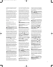
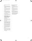
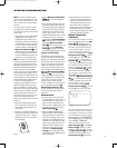
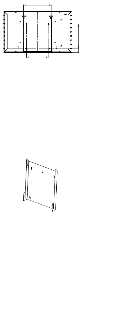
The bracket must be installed in wood
studs; there is no wall-anchor option. The
slot holes in the bracket are designed to
accommodate 16-inch on-center wall
studs. See the illustration (Figure 1) for
the dimensions of the bracket.
Figure 1
The bracket must be installed using four
lag bolts, each at least 1/4 inch in diame-
ter. Each bolt must be long enough to
engage in the stud by at least 2 inches.
In order to avoid splintering the wall
studs, it is necessary to drill pilot holes
for each lag bolt.
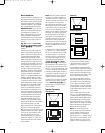
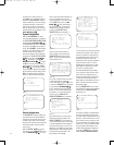
Use a carpenter’s level to ensure that the
bracket is installed squarely. You will
observe that the bracket uses slotholes
to assist you in making adjustments to
level the bracket before fully tightening
the lag bolts.
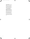
Figure 2
Once the bracket has been installed. Two
people may carefully lift the CVPD50
screen and lower it onto the bracket so
that the two hooks on either side of the
bracket engage in the openings on the
underside of the CVPD50.
Installing the CVPD50 Plasma Display
On the Included Credenza Stand
If wall-mounting the CVPD50 plasma
screen is not convenient or practical, you
may prefer to install the CVPD50 on a cre
-
denza or other sturdy piece of furniture
using the included credenza stand. In
addition to offering an elegant appear
-
120
25
10x45 32
581,7
80,50
50,50
4,50
/2x
48
5x45
106
33,7
∞
5
14,5
33,7
∞
9
514
13
4
90
20
3x45 /4x
636,6
30/4x
R
4,
50
12,35
450
R
203,
20
R
493,75
01
Gratseite
0
2
0
2
Abwicklung
M1:5
1238,8 1
754,8 1
950,1 3
515 1
1106,50
622
255,6 2
80,61 5
713,40 1
88,34 3
20-1/4"
5
-1/2"
1
6"
17-3/4"
INSTALLING AND CONNECTING THE EQUIPMENT
CVR700 OM 12/17/04 4:24 PM Page 39