SMV 3000 Transmitter User’s Manual 1/9972
6.9 FlowConf Configuration - PV4, Continued
Damping
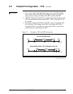
Adjust the damping time constant for flow measurement (PV4) to reduce
the output noise. We suggest that you set the damping to the smallest
value that is reasonable for the process.
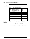
The damping values (in seconds) for PV4 are:
0.00
d
, 0.5, 1.0, 2.0, 3.0, 4.0, 5.0,
10.0, 50.0 and100.0
d
Factory setting.
ATTENTION
The electrical noise effect on the output signal is partially related to the
turndown ratio of the transmitter. As the turndown ratio increases, the
peak-to-peak noise on the output signal increases. See the Damping
paragraphs in subsection 6.6 for a formula to find the turndown ratio using
the pressure range information for your transmitter.
Low Flow Cutoff for
PV4
For calculated flow rate (PV4), set low and high cutoff limits between 0
and 30% of Upper Range Limit for PV4 in engineering units.
• Low Flow Cutoff: Low (0.0 = default)
High (0.0 = default)
Background
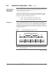
You can set low and high low flow cutoff limits for the transmitter output
based on the calculated variable PV4. The transmitter will clamp the
current output at zero percent flow when the flow rate reaches the
configured low limit and will keep the output at zero percent until the flow
rate rises to the configured high limit. This helps avoid errors caused by
flow pulsations in range values close to zero. Note that you configure limit
values in selected engineering units between 0 to 30% of the upper range
limit for PV4.
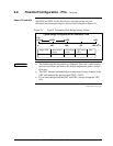
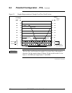
Figure 25 gives a graphic representation of the low flow cutoff action for
sample low and high limits in engineering units of liters per minute.
ATTENTION
If the flow LRV is not zero, the low flow cutoff output value will be
calculated on the LRV and will not be 0 %.
Continued on next page


