


190 SMV 3000 Transmitter User’s Manual 1/99
C.3 Dynamic Compensation Flow Equation, Continued
Table C-5 Superheated Steam Configuration Example, continued
Step Action
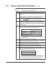
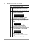
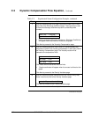
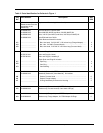
7
Enter the following lower and upper Reynolds number limits in each
entry field of the Discharge Coefficient page. These values are used
to clamp the discharge coefficient equation at these Reynolds
numbers:
Lower Limit = 200,000
Upper Limit = 1,200,000
• Graph coordinates (Reynolds Number vs. Discharge Coefficient)
will appear when the mouse is clicked on the graph.
Click Next to proceed to the Viscosity Compensation page.
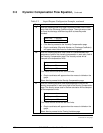
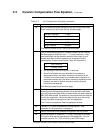
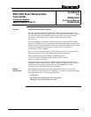
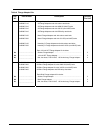
8
Enter the following equation order (order 4 is recommended) and
temperature limits for the viscosity compensation in each entry field of
the Viscosity Compensation page. The viscosity values will be
clamped at the temperature limits.
Order = 4
Low Temp = 297
High Temp = 400
Click Yes to refit the curve with the new limits.
• Graph coordinates will appear when the mouse is clicked on the
graph.
Click Next to proceed to the Density Variables page.
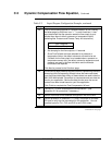
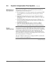
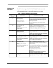
9
Enter the relevant process information from the Orifice Sizing Data
Sheet in each entry field of the Density Variables page.
Isentropic Exponent * = 1.4044
Click Next to proceed to the Flowing Variables page.
* Isentropic Exponent is also called the Ratio of Specific Heats.
Continued on next page