1/99 SMV 3000 Transmitter User’s Manual 139
12.1 Replacement Parts, Continued
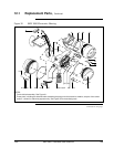
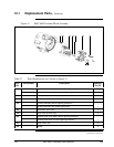
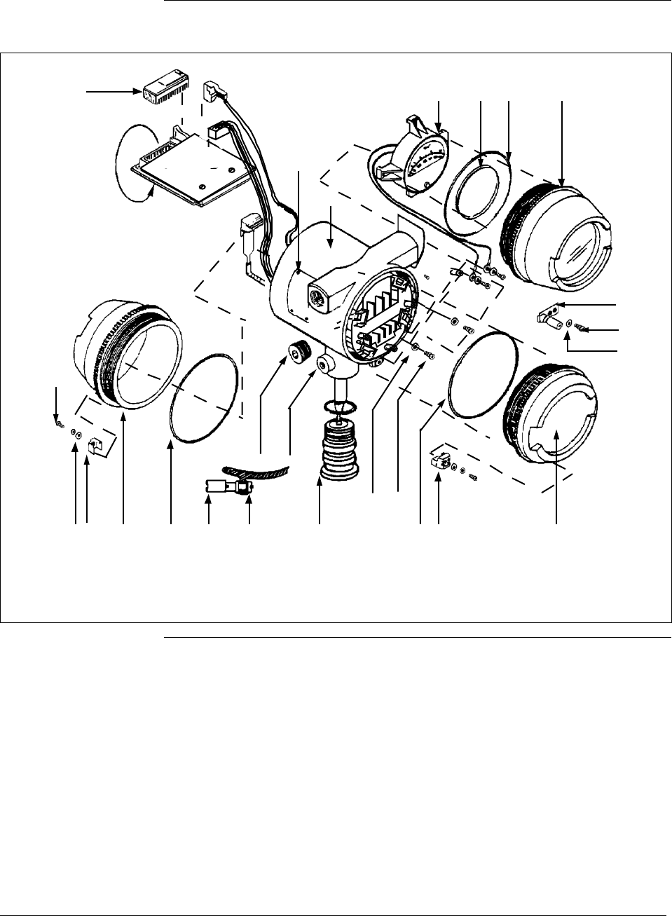
Figure 30 SMV 3000 Electronics Housing
3
4K2 5
K4
6
K10 K9 K2 K8
7
K7 See note 2
K5 K4
K6
K2
K12 K13
K11
9
K1
K3
K5
See
note 1
2
1
NOTES:
1. Terminal block assembly. See Figure 31.
2. These parts, including the attached cable assembly that plugs into the electronics module, are part of the center
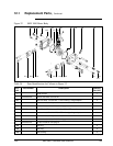
section – shown for reference purposes only. See Figure 32 for meter body parts.
Continued on next page


