


1/99 SMV 3000 Transmitter User’s Manual vii
Figures and Tables
Figure 1 SMV 3000 Transmitter Handles Multiple Process Variable
Measurements and Calculates Flow Rate ................................................................ 4
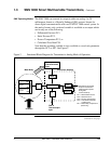
Figure 2 Functional Block Diagram for Transmitter in Analog Mode of Operation.................. 5
Figure 3 Functional Block Diagram for Transmitter in Digital DE Mode of
Operation. ................................................................................................................. 6
Figure 4 Smartline Configuration Toolkit................................................................................. 7
Figure 5 Typical SFC Communication Interface ..................................................................... 8
Figure 6 Typical SMV 3000 Transmitter Order Components................................................ 11
Figure 7 Typical Mounting Area Considerations Prior to Installation..................................... 17
Figure 8 Typical Bracket Mounted Installations..................................................................... 24
Figure 9 Leveling a Transmitter with a Small Absolute Pressure Span. ............................... 28
Figure 10 Typical 3-Valve Manifold and Blow-Down Piping Arrangement.............................. 29
Figure 11 Transmitter Location Above Tap for Gas Flow Measurement ................................ 31
Figure 12 Transmitter Location Below the Tap for Liquid or Steam Flow
Measurement.......................................................................................................... 32
Figure 13 Operating Range for SMV 3000 Transmitters......................................................... 36
Figure 14 SMV 3000 Transmitter Terminal Block ................................................................... 37
Figure 15 RTD Input Wiring Connections. .............................................................................. 42
Figure 16 Thermocouple Input Wiring Connections................................................................ 42
Figure 17 Ground Connection for Lightning Protection........................................................... 43
Figure 18 SCT Hardware Components................................................................................... 46
Figure 19 Write Protect Jumper Location and Selections with Daughter PCB
Removed................................................................................................................. 51
Figure 20 SMV On-line Configuration Process ....................................................................... 47
Figure 21 Square Root Dropout Points for PV1...................................................................... 59
Figure 22 Typical Range Setting Values for PV3.................................................................... 68
Figure 23 Example of LRV and URV Interaction..................................................................... 69
Figure 24 Typical Volumetric Flow Range Setting Values ...................................................... 74
Figure 25 Graphic Representation of Sample Low Flow Cutoff Action. .................................. 76
Figure 26 Typical SCT or SFC and Meter Connections for SMV Start up
Procedure. .............................................................................................................. 92
Figure 27 Location of Failsafe Jumper on main PWA of Electronics Module........................ 101
Figure 28 Typical PV1 or PV2 Range Calibration Hookup.................................................... 116
Figure 29 Major SMV 3000 Smart Multivariable Transmitter Parts Reference. .................... 138
Figure 30 SMV 3000 Electronics Housing............................................................................. 139
Figure 31 SMV 3000 Terminal Block Assembly.................................................................... 142
Figure 32 SMV 3000 Meter Body.......................................................................................... 143
Figure A-1 Typical PM/APM/HPM SMV 3000 Integration Hierarchy. ..................................... 151
Figure A-2 Mapped Parameters are Basis for Data Exchange............................................... 153
Figure A-3 Sixteen AI Points per STIMV IOP ......................................................................... 155
Figure A-4 AI Point for Each Transmitter Input....................................................................... 156
Figure A-5 Connection Rule Example. ................................................................................... 161
Figure A-6 Detail Display with PV Number and Number of PVs Field.................................... 169
Figure A-7 Example of DECONF Download Error Message. ................................................. 171