SMV 3000 Transmitter User’s Manual 1/99172
Appendix B– Configuration Record Sheet, Continued
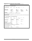
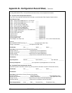
1b. Static Pressure - PV2 - Configuration Section
PV2 Damping (sec.): 0.0 ___
0.16 ___ 0.32 ___ 0.48 ___ 1 ___ 2 ___
4 ___ 8 ___ 16 ___ 32 ___
PV2 Eng. Units: "H2O_39F ___ PSI ___ MPa ___ bar ___
(Static Pressure) kg/cm^2 ___ mmH2O_4C ___ mmHg_0C ___ KPa ___
mbar ___ g/cm^2 ___ inHg_32F ___ ATM ___
mH2O_4C ___ "H2O_68F ___ "H2O_60F ___
PV2 Range: LRV _____ URV _____
(default depends on SMV 3000 model number - specify gauge or absolute)
Barometric Pressure: ___________
(If using SMV 3000 in a flow application and you specify the SMG170 model number, enter the barometric pressure)
(Default is 14.7 psia)
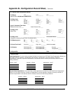
1c. Process Temperature - PV3 - Configuration Section
PV3 Damping (sec.): 0.0 ___
0.3 ___ 0.7 ___ 1.5 ___ 3.1 ___ 6.3 ___
12.7 ___ 25.5 ___ 51.1 ___ 102.3 ___
PV3 Probe Type: PT 100 D RTD ___ Type E TC ___ Type J TC ___
Type K TC ___ Type T TC ___
PV3 Eng. Units: deg. C ___ deg. F ___ deg. R ___
PV3 Range: LRV _____ URV _____
(defaults are -200 and 450 deg. C)
PV3 Cold Junc. Comp.: Internal ___ External ___ ECJT: _____
(Only for Themocouple. If external, specify the temp. in the ECJT slot)
PV3 TC Fault Detection: On ___ Off ___
PV3 Output Charact.: Linear ___ Non-Linear ___
Continued on next page


