


SMV 3000 Transmitter User’s Manual 1/99158
A.4 Installation, Continued
Connection Rule,
continued
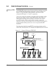
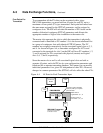
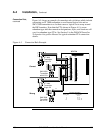
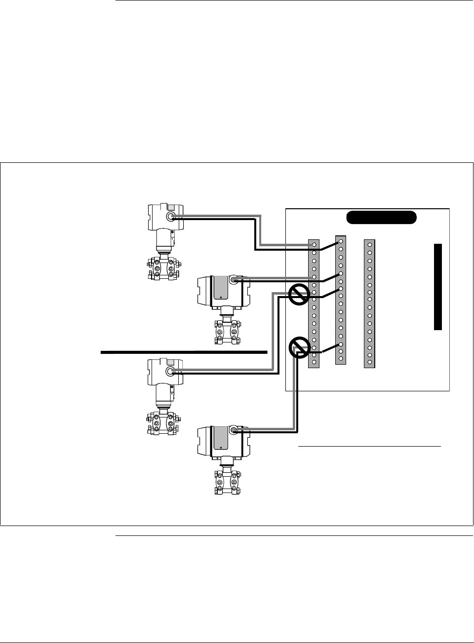
Figure A-5 shows an example of connection rule violations which include
connecting an ST 3000 transmitter to an allocated logical slot and an
SMV 3000 transmitter to a slot that causes a logical slot to wrap around
the IOP boundary. Note that the FTA shown in Figure A-5 is a non-
redundant type and the connection designations, styles, and locations will
vary for redundant type FTAs. See Section 5 in the PM/APM Smartline
Transmitter Integration Manual for typical redundant FTA connection
details.
Figure A-5 Connection Rule Example.
9
10
11
12
13
14
15
16
1
2
3
4
5
6
7
8
SMV 3000
Transmitter
with 4 PVs
TB1
TB2
XMTR
+24V
PV
IN (+)
COM
IN (-)
_
+
STI FTA
9
10
11
12
13
14
15
16
1
2
3
4
5
6
7
8
9
10
11
12
13
14
15
16
1
2
3
4
5
6
7
8
TB3
_
+
_
+
_
+
Correct
Wrong
SMV 3000
Transmitter
with 4 PVs
ST 3000
Transmitter
Single PV
ST 3000
Transmitter
Single PV
Terminal Designation
Master Slots Logical Slots
1 2, 3, 4
5 6, 7, 8
9 10, 11, 12
13 14, 15, 16