


30 SMV 3000 Transmitter User’s Manual 1/99
4.5 Wiring SMV 3000 Transmitter
CE Conformity Special
Conditions (Europe)
You must use shielded, twisted-pair cable such as Belden 9318 for all
signal/power wiring.
Summary
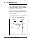
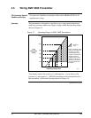
The transmitter is designed to operate in a two-wire power/current loop
with loop resistance and power supply voltage within the operating range
shown in Figure 13.
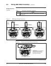
Figure 13 Operating Range for SMV 3000 Transmitters
0 10.8 16.28 20.63 25 28.3 37.0 42.4
250
450
650
800
1200
1440
Operating Voltage (Vdc)
= Operating
Area
NOTE: A minimum of 250
0hms of loop resistance is
necessary to support
communications. Loop
resistance equals barrier
resistance plus wire
resistance plus receiver
resistance. Also 45 volt
operation is permitted if
not an intrinsically safe
installation.
Loop
Resistance
(ohms)
21012
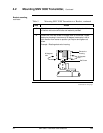
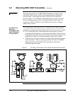
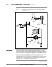
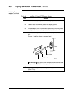
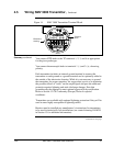
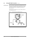
You simply connect the positive (+) and negative (–) loop wires to the
positive (+) and negative (–) SIGNAL terminals on the terminal block in
the transmitter’s electronics housing shown in Figure 14.
Continued on next page