96 SMV 3000 Transmitter User’s Manual 1/99
8.3 Changing Default Failsafe Direction, Continued
Procedure, continued
Table 26 Cutting Failsafe Jumper
Step Action
1
Connect SCT to SMV and establish communications. (See
subsection 5.2 for procedure, if necessary.)
2
Be sure any switches that may trip alarms or interlocks associated
with analog loops are secured or turned off.
3
Open the Status Tab Card. Read and record the gross and detailed
status messages of the transmitter.
4
Turn OFF transmitter power. Loosen end-cap lock and unscrew end
cap from electronics side of transmitter housing.
5
Release retaining clip and unplug flex tape and power connectors
from Main PWA underneath module. Unplug temperature input
connector from Daughter PWA underneath module. Loosen two
captive mounting screws on top of module, and then carefully pull
module from housing.
6
ATTENTION
You may be able to cut the failsafe jumper without
removing the molding and Daughter PWA as noted in this Step and
the next one. Just be sure you can identify the jumper and don’t
damage other components in the process of cutting it.
Remove screw holding connector molding/retaining clip to Main PWA
and remove molding.
7
Remove two retaining screws and carefully pull Daughter PWA
straight up to unplug it from connector on Main PWA.
8
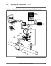
With component side of PWA facing you, locate failsafe jumper and
cut it in half with small wire cutter such as dykes. See Figure 27. This
changes failsafe action from upscale to downscale.
9
Reverse applicable previous steps to replace PWA/module.
Continued on next page


