


1/99 SMV 3000 Transmitter User’s Manual 157
A.4 Installation
Mounting
Assumptions
We assume that you have physically mounted the integration components
in accordance with appropriate instructions in this manual and the
TDC 3000
X
bookset.
WARNING
Before you make any wiring connections, use the SCT to set the PV Type
to PV1 for transmitters operating in DE mode; or if the transmitter is in
the analog mode, use the SCT 3000 set the Analog Output Selection to
PV1 and select Analog as the communication mode. Otherwise, multiple
PVs could conflict with other slots causing contention problems and bad
PV indications.
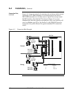
Wiring Connections
You wire the SMV 3000 transmitter for integration the way you would any
other Smartline transmitter. See Section 5 in the PM/APM Smartline
Transmitter Integration Manual for details.
Connection Rule
If the SMV 3000 transmitter will provide multiple inputs (PVs), the FTA
screw terminals used for the transmitter’s DE output connection identify
the physical (or master) slot for the transmitter’s PVs. In this case, be sure
• No other Smartline transmitters are connected to consecutive FTA
screw terminals that are allotted as logical slots for the transmitter’s
other PVs.
• Consecutive logical slots allotted for the transmitter’s other PVs do not
cross over IOP boundaries from 8 to 9 or wrap around an IOP boundary
from 8 to 1 or 16 to 9.
Continued on next page