


1/99 SMV 3000 Transmitter User’s Manual 33
4.5 Wiring SMV 3000 Transmitter, Continued
Wiring connections,
continued
Table 7 Wiring the Transmitter, Continued
Step Action
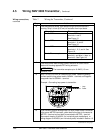
3
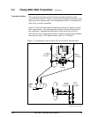
Feed temperature sensor input leads through conduit entrance in
housing. Strip 1/4 inch (6.35 mm) of insulation from input leads.
If input is from … Then…
2-wire RTD connect RTD leads to
terminals 1 and 3.
See Figure 15.
3-wire RTD connect RTD leads to
terminals 1, 2, and 3.
See Figure 15.
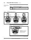
4-wire RTD connect RTD leads to
terminals 1, 2, 3, and 4. See
Figure 16.
2-wire Thermocouple connect minus (–) lead to
terminal 1 and plus (+) lead to
terminal 3. See Figure 16.
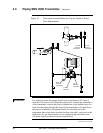
4
Feed loop power leads through conduit entrance on other side of
electronics housing opposite RTD wiring entrance.
ATTENTION
The transmitter accepts up to 16 AWG (1.5 mm
diameter) wire.
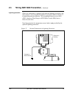
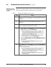
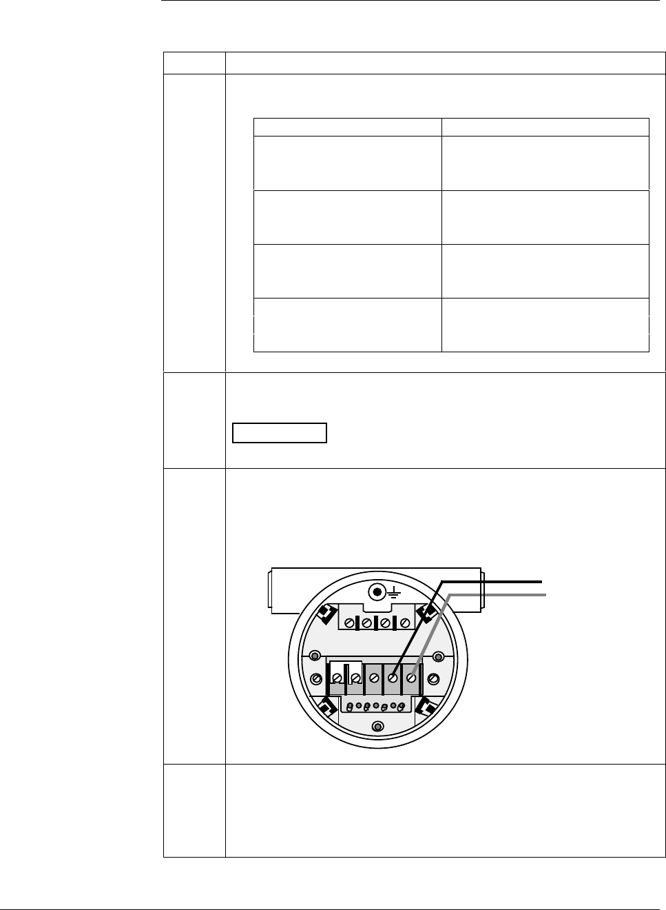
5
Strip 1/4 inch (6.35 mm) of insulation from leads. Observing polarity,
connect positive loop power lead to SIGNAL + terminal and negative
loop power lead to SIGNAL – terminal.
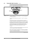
Example - Connecting loop power to transmitter.
+
_
Loop
Power
TEST SIG
–
+
–
+
METER L SIGNAL
12
TC
34
–––
++
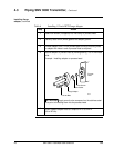
6
If you have an optional analog meter, be sure jumper strap is removed
from across METER terminals, yellow lead from meter is connected to
METER – terminal and red lead is connected to METER + terminal.
See control drawing 51404251 (for intrinsically safe installations) or
wiring diagram 51404250 (non-intrinsically safe) included in Section 13.
Continued on next page